
Mass flow meter and mass flow controller

一种质量流量计、流量计算的技术,应用在流量传感器领域,能够解决流量测量精度降低、测量流量误差、测量流量的误差不同等问题,达到减小误差、提高流量测量精度的效果

Active Publication Date: 2010-06-30
HORIBA STEC CO LTD
View PDF5 Cites 25 Cited by
  • Summary
  • Abstract
  • Description
  • Claims
  • Application Information

AI Technical Summary

Problems solved by technology

[0005] However, if the gas supply pressure (primary side pressure) in the installed main flow path is changed (for example, 100 kPa) in the above-mentioned mass flowmeter, an error will occur in the measured flow rate, and there is a problem that the accuracy of the flow rate measurement will decrease.
[0006] In addition, there is also a problem that the error in the measured flow rate due to the change of the primary side pressure varies depending on the type of sample gas.

Method used


Image

  • Mass flow meter and mass flow controller
  • Mass flow meter and mass flow controller
  • Mass flow meter and mass flow controller

Examples


no. 1 approach

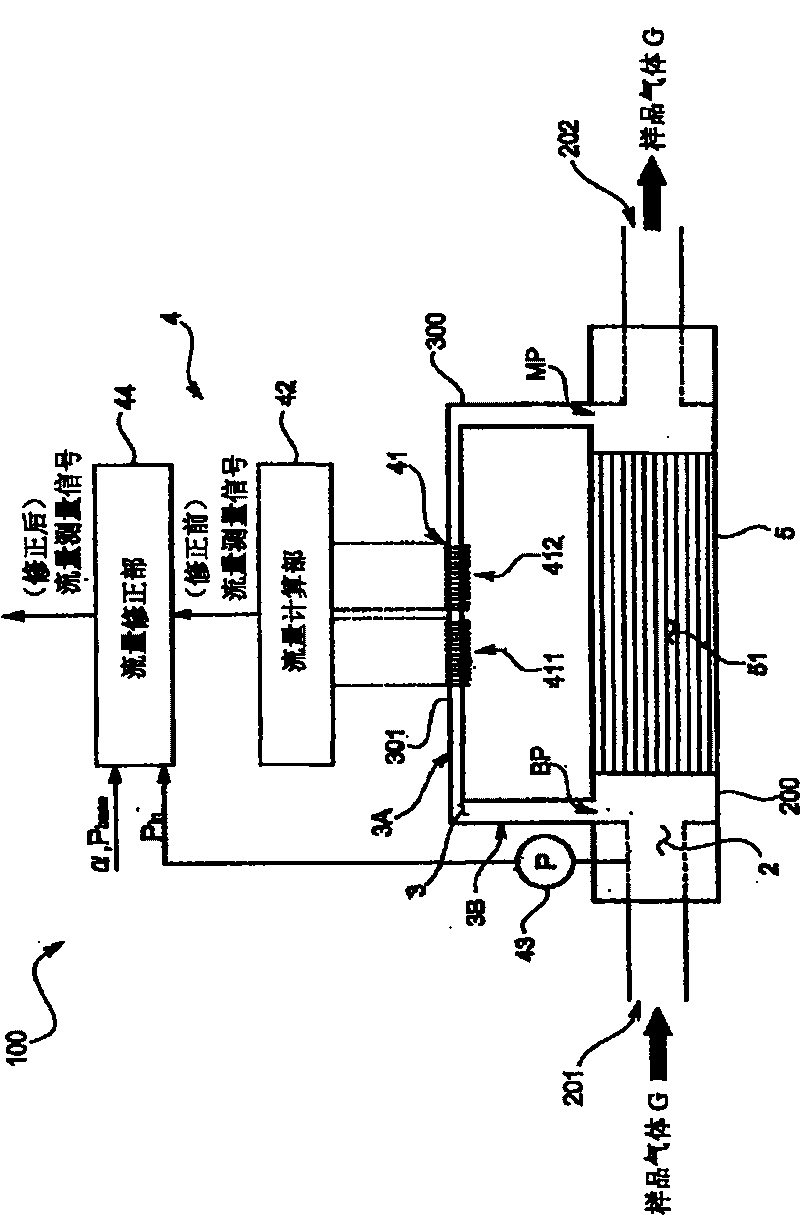
[0054] A first embodiment of the mass flow meter 100 of the present invention will be described below with reference to the drawings. in addition, figure 1 It is a schematic diagram showing the configuration of the mass flowmeter 100 of this embodiment.

[0055]

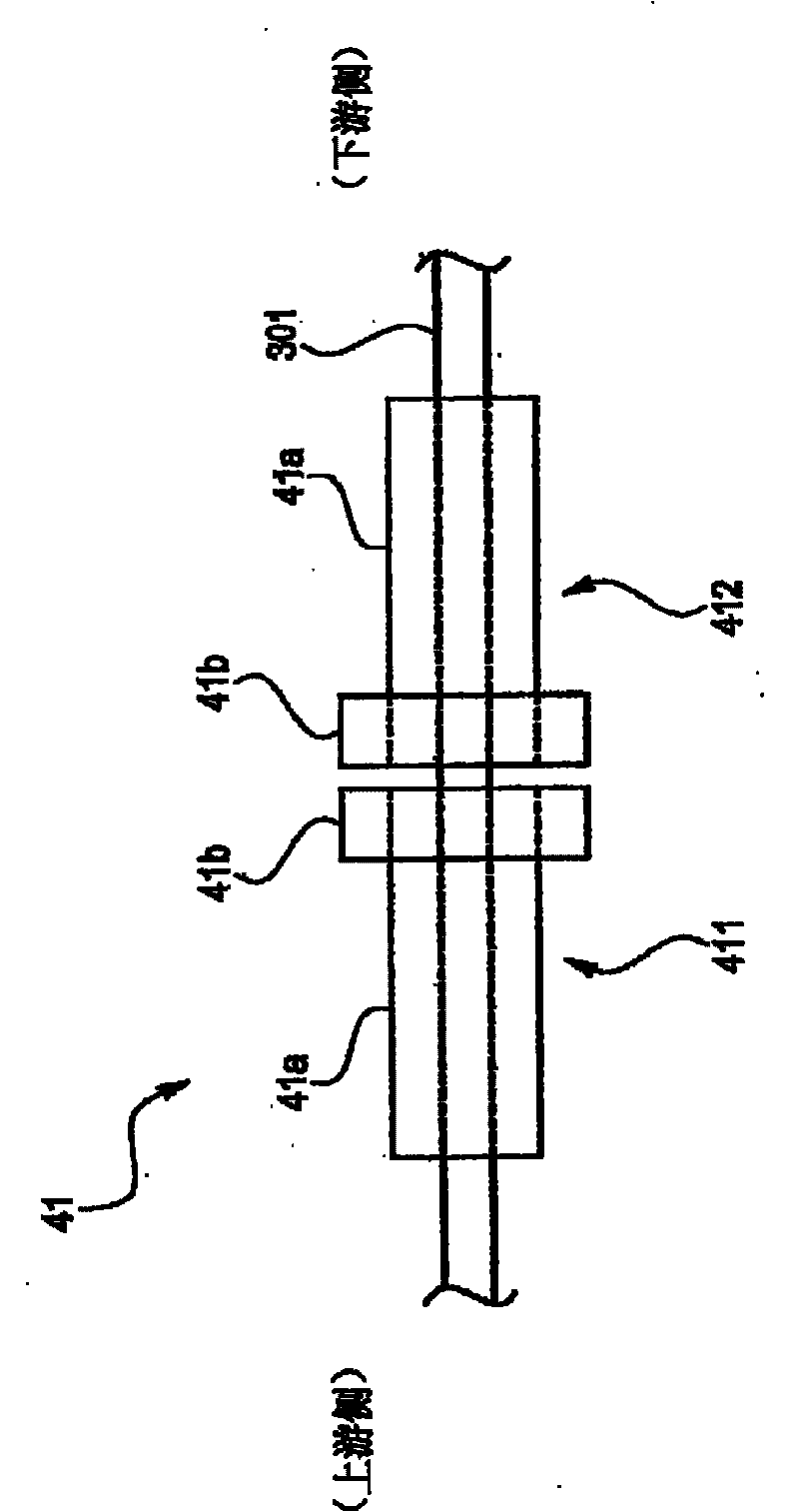
[0056] The mass flowmeter 100 of this embodiment is a thermal mass flowmeter, including: a sample gas (such as SF 6 The main flow path 2 through which the semiconductor processing gas such as) G flows; the sensor flow path 3 is branched from the main flow path 2 to split the sample gas G, and the flow rate Q of the sample gas G raw To detect; the flow detection mechanism 4, the flow Q of the sample gas G raw detection; and a laminar flow element 5 disposed between the branch point BP and the confluence point MP of the sensor flow path 3 in the main flow path 2 and having a plurality of internal flow paths 51 .

[0057] Hereinafter, each part 2-5 is demonstrated.

[0058] The main passage 2 is formed by a substant...

no. 2 approach

[0084] Next, a second embodiment of the mass flowmeter 100 of the present invention will be described. The mass flow meter 100 of this embodiment is as Figure 5 As mentioned above, it further includes a function data storage unit D1, and the function of the flow correction unit 44 is different from that of the flow correction unit 44 in the first embodiment.

[0085] The function data storage unit D1 stores the relational data, the relational data is the reference pressure P base In the following approximate formula (2) obtained by approximating the error [%] between the flow rates with a predetermined function (a linear formula in this embodiment), coefficient a (slope (slope) a) and coefficient b ( Relational expression of intercept b) relative to gas physical property value. This relational expression data is previously input by a user or the like through an input unit.

[0086] [mathematical formula 4]

[0087] Error[%]=a×Q raw +b...(2)

[0088] However, the slope a...


PUM


Abstract

In order to improve a measurement accuracy of a mass flow meter, the mass flow meter comprises a flow rate calculating section that obtains an output signal from a sensor section having a thermosensitive resistive element arranged in a flow channel where a sample gas flows and that calculates a flow rate of the sample gas, a pressure measuring section that measures a primary side pressure in the flow channel, and a flow rate correcting section that corrects the measured flow rate obtained by the flow rate calculating section by the use of the primary side pressure obtained by the pressure measuring section and a gas coefficient determined by an isobaric specific heat of the sample gas.

Description

technical field [0001] The present invention relates to a flow sensor, in particular to a flow sensor capable of performing high-precision flow measurement for each sample gas. Background technique [0002] Regarding this type of mass flowmeter, there is known a thermal mass flowmeter comprising: a main flow path through which sample gas flows; a sensor flow path branched from the main flow path to divide the flow of sample gas, and provided with a control for the sample gas. A flow detection mechanism for detecting mass flow; and a bypass flow path, which is arranged between the branch point and the confluence point of the sensor flow path on the main flow path. Furthermore, in this thermal mass flowmeter, the flow detection mechanism includes: an upstream side sensor unit and a downstream side sensor unit, and two thermistors (thermal resistors) are placed on the outside of a thin metal hollow tube forming a sensor flow path. ) formed in a coil shape; and a bridge circuit...

Claims


Application Information

Patent Timeline
Patent Type & Authority Applications(China)
IPC IPC(8): G01F1/86G05D7/06
CPCG01F5/00G01F1/6842G05D7/0635G01F1/6847Y10T137/7761Y10T137/7759G01F1/36G01F1/88G01L7/08
Inventor 矶部泰弘堀之内修田中祐纪山口正男古川幸正
Owner HORIBA STEC CO LTD
Learn More