Center shaft type electromobile motor

An electric vehicle, shaft-type technology, applied in the direction of electric vehicles, motors, electric components, etc., can solve the problems of insufficient assembly structure, limited power supply mileage, high energy consumption of electric power supply, etc., to achieve volume reduction and continuous mileage extension , The effect of reducing electric energy consumption

Active Publication Date: 2010-06-30
BOSCH NINGBO E SCOOTER MOTOR
View PDF6 Cites 17 Cited by
  • Summary
  • Abstract
  • Description
  • Claims
  • Application Information

AI Technical Summary

Problems solved by technology

However, the motor of this patent adopts an outer rotor structure, and the transmission and separation of the motor torque are realized through the clutch of the pawl and the pressure plate seat. The assembly structure is not compact enough, and the overall volume is relatively large. When the motor is in the electric running state, the power of the pedals is separated, and the vehicle is completely driven by electricity, and the pedals cannot work at the same time. When the human pedals are used to drive the vehicle forward, the electric drive of the motor is separated, and the vehicle is It is completely driven by human pedals. Therefore, the electric vehicle motor of this patent can only work in one of the electric or pedal states, and cannot achieve power superposition in the state of electric and pedal work at the same time, making the energy consumption of the electric power supply relatively low. High, the mileage of the power supply is limited

Method used


Image

  • Center shaft type electromobile motor
  • Center shaft type electromobile motor
  • Center shaft type electromobile motor

Examples


Embodiment Construction

[0024] The present invention will be further described in detail below in conjunction with the accompanying drawings and embodiments.

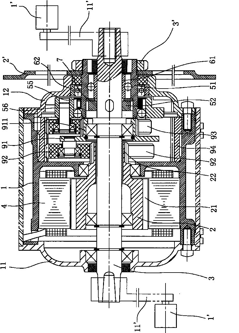
[0025] Such as Figure 1 to Figure 6 As shown, it is a schematic diagram of the structure of the electric vehicle motor in this embodiment. The electric vehicle motor uses the central shaft 3 of the electric vehicle as the motor shaft, and is a high-speed brushless motor with an inner rotor structure, which can realize machine embedding when the motor is mass-produced. Suitable for mass production; Among them, electric vehicle motors include

[0026] The casing 1 is provided with a front end cover 11 and a rear end cover 12 forming a closed cavity with the casing 1 at both ends of the casing 1 .

[0027] The rotor 2 is rotatably arranged on the central shaft 3 of the electric vehicle and is positioned by bearings. The two ends of the central shaft 3 are also fixedly connected with pedals 1' for human pedaling through cranks 11'.

[0028] The...


PUM


Abstract

The invention relates to a center shaft type electromobile motor, which comprises a casing, a rotor, a stator, a retarding mechanism and a clutch. The center shaft type electromobile motor is characterized in that a first inner ring of a first clutch is fixedly connected with a center shaft, the first inner ring can do a unidirectional rotation, which is opposite to a pedal direction, relative to a first outer ring, the first outer ring is connected with a chain wheel, and a spring abuts against one end of a rolling column so as to ensure that the rolling column is provided with a trend to move to a small end of an open slot all the time; a second outer ring of a second clutch is connected with an output end of the retarding mechanism, the inner wall of the second outer ring is provided with a wedge-shaped slope along a circumferential direction, an end face of a second inner ring is also provided with a ratchet along a circumferential direction, and the ratchet and the wedge-shaped slope are matched to enable that the second outer ring can only do a unidirectional rotation, which is opposite to the rotation direction of the rotor, relative to the second inner ring. Compared with the prior art, by adopting a combined type bidirectional clutch, the invention can not only realize the function of motor driving or pedaling respectively, but also can realize the simultaneous work of the motor driving and the pedaling, thereby realizing output power superposition and ensuring that an electromobile saves electric assistance during running.

Description

technical field [0001] The invention relates to a motor of an electric vehicle, in particular to a central motor with the central shaft of the electric vehicle as a drive shaft. Background technique [0002] In daily life, the motors used in our common electric bicycles or electric tricycles are usually hub motors or mid-mounted motors. Among them, the hub motor is generally driven by the front wheel or the rear wheel. The motor is installed at the axle core of the front wheel or the rear wheel of the electric bicycle or tricycle. The front and rear wheels need to be made of integral rims or spokes. , the spokes are easy to break, because the hub motor is directly installed on the center shaft of the front wheel or rear wheel, the transmission torque of the motor is small, and the efficiency is low, and the configuration center of gravity of the hub motor is not at the center of the vehicle, which makes the stability of the vehicle poor; the center motor Generally installed...

Claims


Application Information

Patent Timeline
Patent Type & Authority Applications(China)
IPC IPC(8): H02K7/112F16D21/00
CPCY02T10/641Y02T10/64
Inventor 罗大铖戴爱国
Owner BOSCH NINGBO E SCOOTER MOTOR
Why Eureka
Try Eureka