Target with metal glass coating and composite material prepared from target

A technology of metallic glass and composite materials, which is applied in the direction of metal material coating process, sputtering plating, ion implantation plating, etc., can solve problems such as difficult mass production and application, difficult processing and production, and inability to master metallic glass coating

Inactive Publication Date: 2010-07-07
METAL INDS RES & DEV CENT
View PDF2 Cites 25 Cited by
  • Summary
  • Abstract
  • Description
  • Claims
  • Application Information

AI Technical Summary

Problems solved by technology

[0005] For example, U.S. Patent No. 4965139 "CORROSION RESISTANT METALLIC GLASS COATINGS" proposes "using multi-target source (target) magnetron sputtering to deposit Based on the technical means of producing glass-metal coatings containing 8-30 atomic percent of boron, silicon, or a combination thereof; the difficulty of this technology lies in the use of multiple target sources to synthesize metallic glass coatings, and the multi-target originates from the coating In the process, not only is it difficult to control the uniformity of the coating thickness, but at the same time, it is also impossible to obtain a large-area metallic glass coating
[0006] In view of the use of a single target (with multiple elements) for coating, it is easier to control the coating process than using multiple targets for coating, and then obtain a coating with uniform thickness and a larger area. US Patent No. 7282123 "COMPOSITE SPUTTER TARGET AND PHOSPHOR The "DEPOSITION METHOD" case revealed the technical means...

Method used


Image

  • Target with metal glass coating and composite material prepared from target
  • Target with metal glass coating and composite material prepared from target
  • Target with metal glass coating and composite material prepared from target

Examples


Embodiment Construction

[0025] Below in conjunction with accompanying drawing and embodiment the present invention is described in detail:

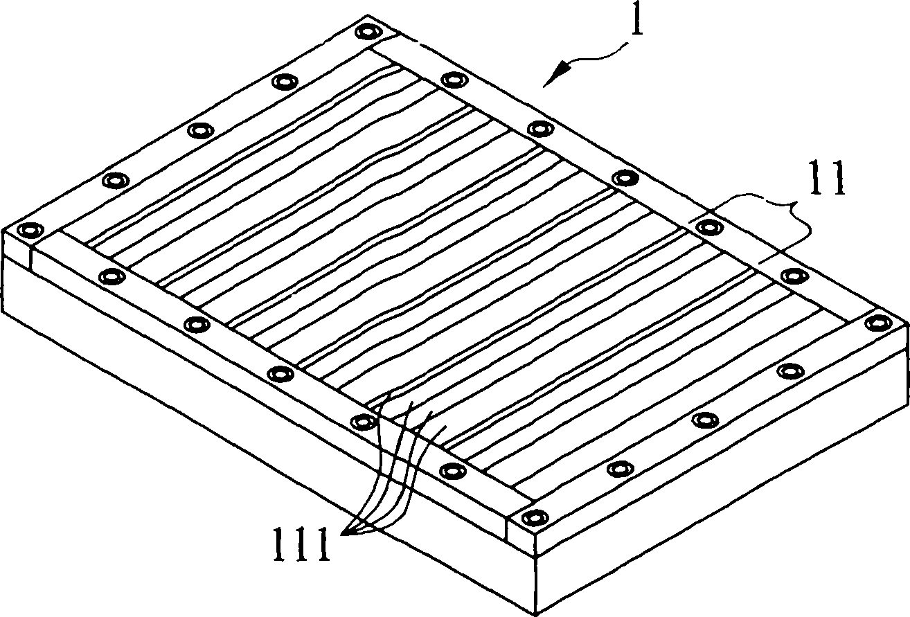
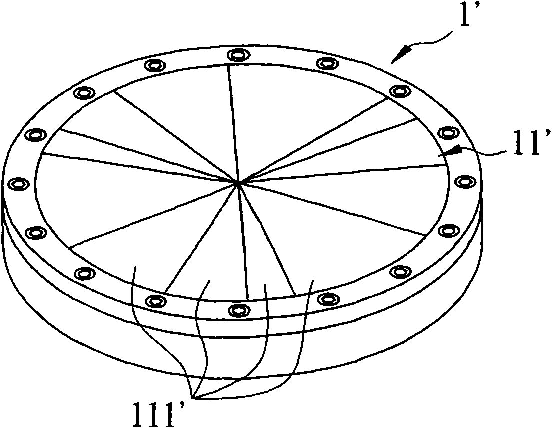
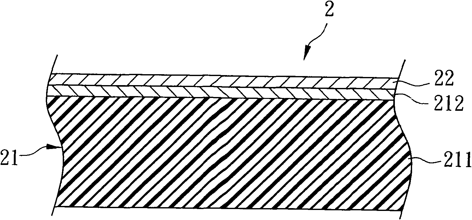
[0026] refer to figure 1 , figure 2 , image 3 ,Such as figure 1 , figure 2 Shown is a first and second preferred embodiment of a target material 1 for forming a metallic glass coating film of the present invention, both of which are suitable for physical vapor deposition process (such as dry plasma vapor deposition), and on the substrate 21 Form metallic glass coating film 22, become as image 3 The shown composite material 2 with metallic glass coating 22 can be widely used in aspects such as metal bipolar plates of fuel cells, surgical knives for medical use, and shell parts of 3C products.

[0027] see first image 3 , the composite material 2 includes a substrate 21 and a metallic glass coating 22 formed by using the target 1 disclosed in the first or second preferred embodiment.

[0028]The substrate 21 has a body 211, and a film body 212 formed o...


PUM

PropertyMeasurementUnit
Diameteraaaaaaaaaa
Central angleaaaaaaaaaa
Hardnessaaaaaaaaaa

Abstract

The invention discloses a target with a metal glass coating. The ZraKbMcNd metal glass coating is formed on a substrate by sputtering, wherein K, M and N are selected from elements in VB group, VIB group, VIIIA group, IB group, IIIA group and IVA group; the atomic radius percentage of any two of K, M and N is not less than 15 percent; and a, b, c and d represent atomic composition percentage, wherein a is more than or equal to 30 percent and less than or equal to 77 percent, b is more than or equal to 11 percent and less than or equal to 50 percent, c is more than or equal to 4 percent and less than or equal to 15 percent, and d is more than or equal to 4 percent and less than or equal to 10 percent. The target is provided with a plurality of fan-shaped coating material units which are spliced into a disc or arranged continuously in a rectangular shape, wherein each coating material unit is provided with four element strips which consist of four metal elements, namely zirconium, K, M and N, and the number ratio of zirconium, K, M and N of all the element strips and the metal glass coating are in a sputtering generation proportional relationship.

Description

technical field [0001] The invention relates to a target material for coating and a composite material with a coating formed by the target, in particular to a target for forming a metallic glass coating and a composite material with a metallic glass coating formed from the target. Background technique [0002] "Metallic glass" is an alloy with an amorphous structure formed by mixing and melting various specific elements and then rapidly cooling and solidifying. It is also called "amorphous alloy" because of its high strength and excellent wear resistance. Mechanical properties, and superplastic forming characteristics at an appropriate temperature, and because of the lack of grain boundaries, it can be finely filled and molded under a lower deformation pressure, so it has been widely valued by all walks of life. [0003] At present, metallic glasses can be roughly divided into several categories such as Zirconium based metallic glass, Magnesium based metallic glass, and Tita...

Claims


Application Information

Patent Timeline
IPC IPC(8): C23C14/14C23C14/34
Inventor 邱松茂朱继文杨国源卓廷彬
Owner METAL INDS RES & DEV CENT
Why Eureka
Try Eureka