Dynamic pressure regulator based on piezoelectric ceramic technology

A technology of dynamic pressure and piezoelectric ceramics, applied in the direction of measuring fluid pressure, instruments, measuring devices, etc., can solve the problems of small pressure amplitude and large distortion.

Inactive Publication Date: 2010-07-07
BEIJING CHANGCHENG METERING TEST TECH INST NO 1 GRP CO CHINA AVIATION IND
View PDF10 Cites 11 Cited by
  • Summary
  • Abstract
  • Description
  • Claims
  • Application Information

AI Technical Summary

Problems solved by technology

The sinusoidal pressure signals generated by the above several sinusoidal pressure generating devices not only have a large degree of distortion in the high frequency range, but also the pressure amplitude becomes very small

Method used


Image

  • Dynamic pressure regulator based on piezoelectric ceramic technology
  • Dynamic pressure regulator based on piezoelectric ceramic technology

Examples


Embodiment 1

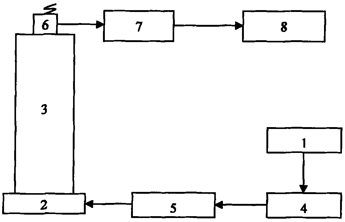
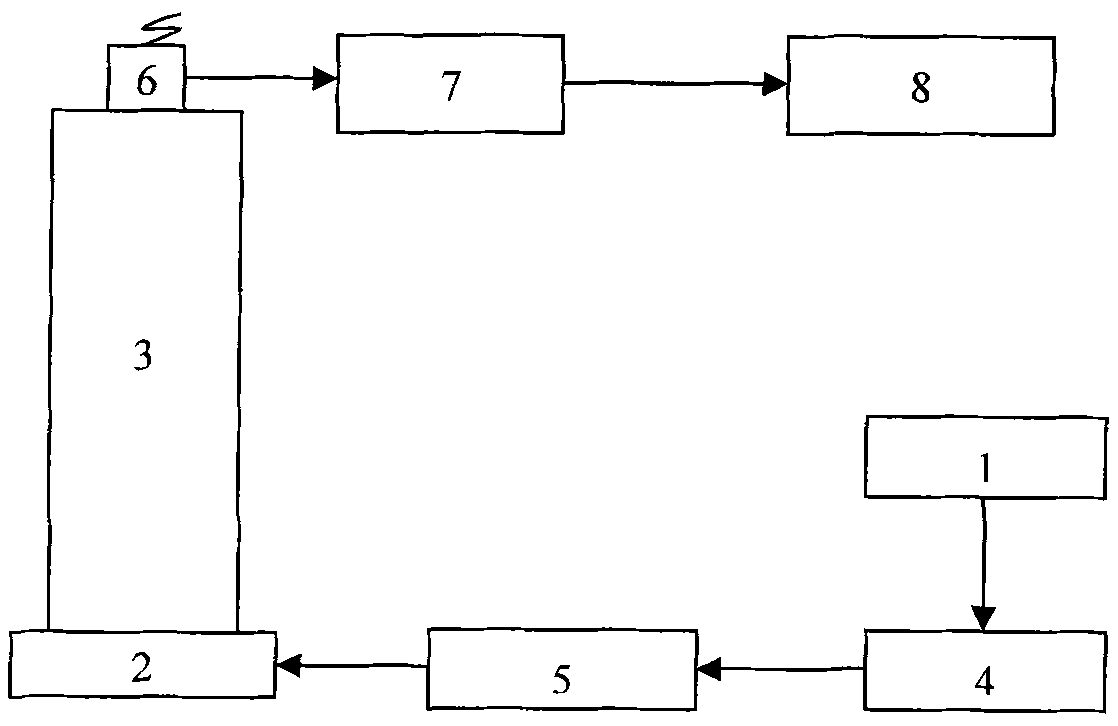
[0020] The voltage excitation circuit part includes a sinusoidal voltage signal generator, a power amplifier and an LC resonant circuit. The output end of the LC resonant circuit is connected to the piezoelectric stack. The piezoelectric stack is placed at the bottom of the resonant pipe. The resonant pipe is made of cylindrical stainless steel. , the interior is filled with water medium, and the excitation signal generated by the LC resonant circuit acts on the piezoelectric stack. By adjusting the frequency of the signal generator, the oscillation frequency of the piezoelectric stack is changed to be equal to the natural frequency of the liquid medium in the resonance pipe to generate resonance. A sinusoidal pressure wave is generated in the top of the resonant pipeline, and an installation hole for installing the pressure sensor to be calibrated is opened on the top of the resonant pipeline. The pressure-amplitude ratio is 1074 when the resonance point is 1kHz.

Embodiment 2

[0022] The voltage excitation circuit part includes a sinusoidal voltage signal generator, a power amplifier and an LC resonant circuit. The output end of the LC resonant circuit is connected to the piezoelectric stack. The piezoelectric stack is placed at the bottom of the resonant pipe, and the resonant pipe is made of cylindrical aluminum. , the interior is filled with oil medium, the excitation signal generated by the LC resonant circuit acts on the piezoelectric stack, and by adjusting the frequency of the signal generator, the oscillation frequency of the piezoelectric stack is changed to be equal to the natural frequency of the liquid medium in the resonant vibration pipeline. Resonance, a sinusoidal pressure wave is generated in the top of the resonant pipe, and the top of the resonant pipe is provided with a mounting hole for installing the pressure sensor to be calibrated. The pressure-amplitude ratio is 981 when the resonance point is 1kHz.


PUM


Abstract

The invention belongs to a dynamic pressure regulating technology, and relates to a dynamic pressure regulator based on the piezoelectric ceramic technology. The dynamic pressure regulator comprises a resonance pipeline, a piezoelectric stack and a voltage energized circuit, wherein the voltage energized circuit comprises a sine voltage signal generator, a power amplifier and an LC resonance circuit. The output end of the LC resonance circuit is connected with the piezoelectric stack which is positioned at the bottom of the resonance pipeline, the inside of the resonance pipeline is filled with liquid medium, and the top of the resonance pipeline is provided with a mounting hole for mounting a pressure sensor to be regulated. In the invention, the frequency of sine pressure wave in the resonance pipeline is convenient to adjust. The operating frequency of the dynamic pressure regulation is higher, and the sine pressure wave under resonance points has great amplitude and little degree of distortion. The amplitude of the sine pressure wave is not reduced along with the increase of the order of the resonance points, and the amplitude of the pressure wave under some high resonance points is even far greater than the amplitude of the pressure wave under low resonance points. The degree of distortion of the sine pressure wave is not increased along with the increase of the frequency.

Description

technical field [0001] The invention belongs to the dynamic pressure calibration technology and relates to a dynamic pressure calibrator based on piezoelectric ceramic technology. Background technique [0002] The sinusoidal pressure signal is the most commonly used periodic signal in dynamic pressure calibration, through which the amplitude-frequency characteristics and phase-frequency characteristics of the pressure sensor can be obtained very accurately. The sinusoidal pressure generators currently used mainly include piston type, turntable type, jet type and standing wave tube. Piston-type sinusoidal pressure generators have the largest peak-to-peak pressure, but their operating frequency is low, only about tens of Hz. Although the working frequency of the jet-type sinusoidal generator can be as high as 10kHz, the peak-to-peak value of the pressure generated by it in the high-frequency range is very small, and the distortion of the sinusoidal waveform is very large. Th...

Claims


Application Information

Patent Timeline
Patent Type & Authority Applications(China)
IPC IPC(8): G01L27/00
Inventor 王玉芳李程陶继增俞锦刘晶杨军
Owner BEIJING CHANGCHENG METERING TEST TECH INST NO 1 GRP CO CHINA AVIATION IND
Why Eureka
Try Eureka