Laser-vision sensing assisted remote teaching method for remote welding

A technology of visual sensing and teaching methods, applied in teaching aids, educational tools, instruments, etc., can solve the problems of long time-consuming adjustment of welding torch position and posture, and achieve the effects of saving teaching time, easy promotion, and good versatility

Inactive Publication Date: 2010-07-07
HARBIN INST OF TECH
View PDF0 Cites 51 Cited by
  • Summary
  • Abstract
  • Description
  • Claims
  • Application Information

AI Technical Summary

Problems solved by technology

[0003] The purpose of the present invention is to solve the problem of long time-consuming adjustment of the remote teaching of complex weld seams that are difficult to complete in remote weld...

Method used


Image

  • Laser-vision sensing assisted remote teaching method for remote welding
  • Laser-vision sensing assisted remote teaching method for remote welding
  • Laser-vision sensing assisted remote teaching method for remote welding

Examples


specific Embodiment approach 1

[0015] Specific implementation mode one: combine figure 1 and figure 2 Describe this embodiment, the method of this embodiment is realized by the following steps:

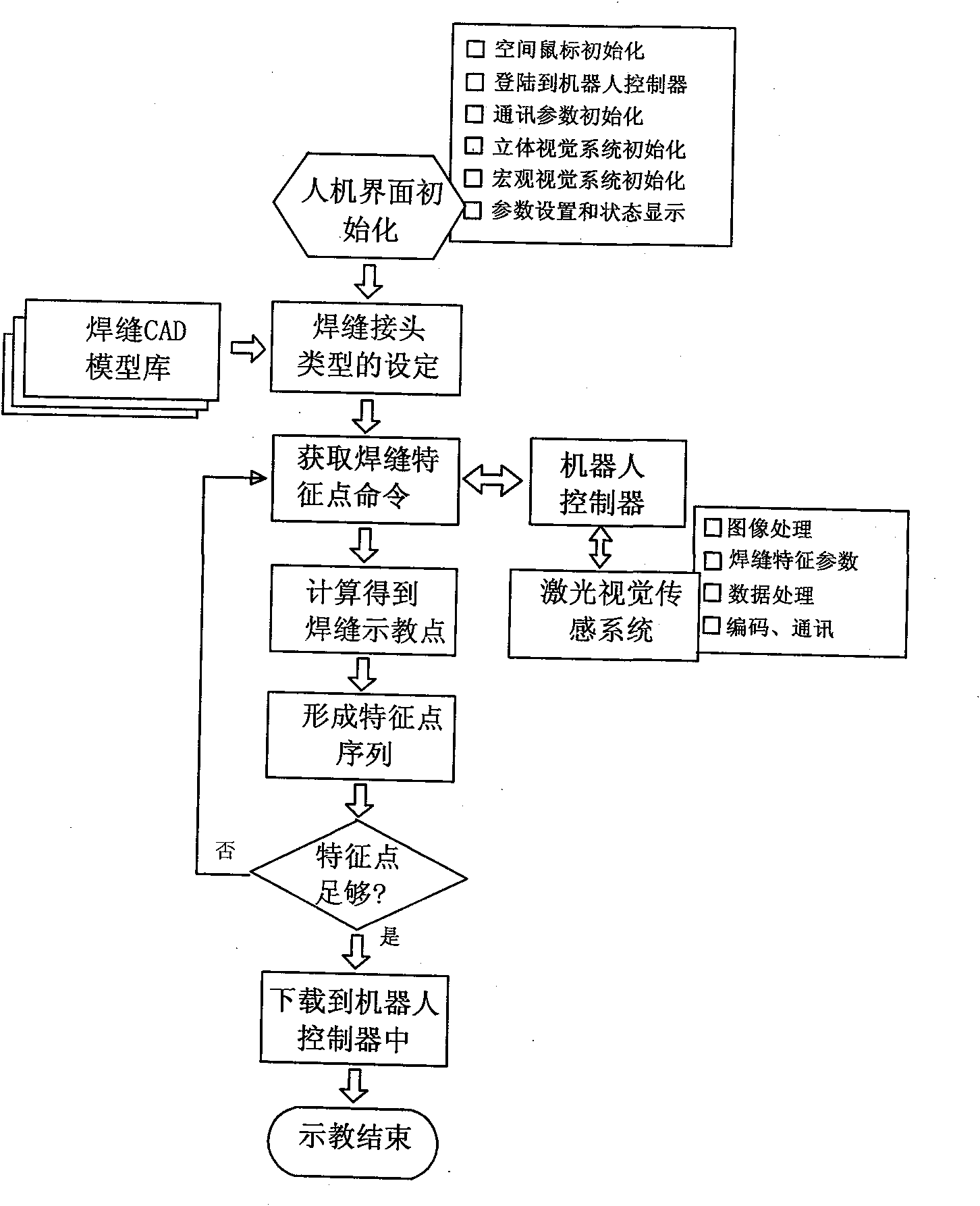
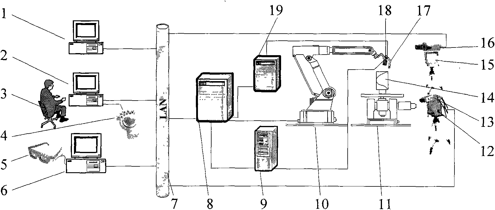
[0016] Step 1: System initialization: first select the central monitoring human-machine interface 2 at the local end as the client to log in to the remote robot controller 8 as the server, and initialize the system, including the initialization of the space mouse 4, the initialization of communication parameters, and the initialization of the stereo vision system And the initialization of the macro vision system, set the system to work in the remote teaching state on the central monitoring man-machine interface 2;

[0017] Step 2: weld joint type setting: manually adjust the macro zoom camera 16 and the second controllable pan / tilt 15 to change the field of view, observe the welding environment at the far end through the macro visual display 1, and manually control the space mouse 4 to send incremental value data...

specific Embodiment approach 2

[0025] Specific implementation mode two: combination figure 1 To describe this embodiment, the robot 10 in Step 3 and Step 5 of this embodiment has six degrees of freedom. Other components and steps are the same as those in Embodiment 1.

specific Embodiment approach 3

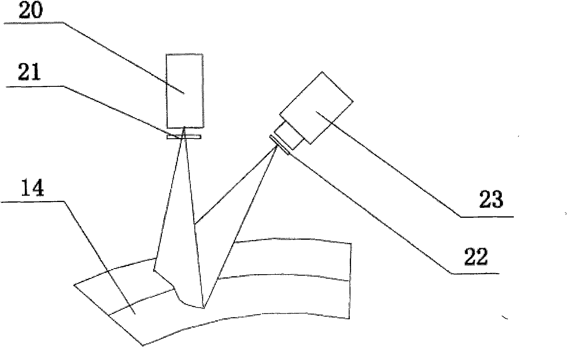
[0026] Specific implementation mode three: combination figure 1 , image 3 and Figure 4 Describe the present embodiment, the feature point of automatically extracting weld seam in the step 3 of present embodiment obtains as follows: welding torch 17 is affixed on the sixth joint of robot 10, and laser vision sensor working head 18 is affixed to welding torch 17 , and calibrated in advance, the installation distance between the laser vision sensor working head 18 and the welding gun 17 is 25mm, the workpiece 14 is positioned on the work platform 11, when the laser vision sensor working head 18 works, the laser in the laser vision sensor working head 18 emits The laser points emitted by the device 20 are converted into laser line stripes by the prism 21 in the laser vision sensor working head 18, reflected by the workpiece 14, and hit the laser vision sensor working head 18 by the filter 22 in the laser vision sensor working head 18. On the CCD 23, according to the principle ...


PUM


Abstract

The invention discloses a laser-vision sensing assisted remote teaching method for remote welding, relating to a remote teaching method for remote welding. The purpose of the invention is to solve the problems of difficult-completed remote teaching of complex weld bead in remote welding and long time consumption of position and attitude adjustment of a welding gun in teaching. The method comprises the following steps: 1. initializing a system; 2. setting a weld joint type; 3. automatically obtaining weld bead feature points; 4. calculating to obtain weld bead teaching points Ti = Ps + Rr; 5. recording and forming a teaching point sequence; 6. judging whether the teaching points are enough; 7. downloading a remote teaching program; 8. and finishing teaching. The method is used for remote welding.

Description

technical field [0001] The invention relates to a remote teaching method for remote welding. Background technique [0002] For welding tasks in extreme environments such as space exploration, underwater construction, and repair of nuclear power plants, the operator cannot be present at the scene, and remote control must be used to complete the welding operation. Remote welding refers to the remote welding that the operator is not at the welding site, and the remote operation robot welding system or automatic welding equipment is used to complete the remote welding. Teaching reproduction is the main operation method of traditional robot welding, and remote teaching is also a key technology to realize remote welding. In the traditional teaching, if the teaching welding seam trajectory is a space curve, only for any teaching point on the path, it is necessary to adjust the position and posture of the welding torch multiple times, and the teaching time is even longer than the w...

Claims


Application Information

Patent Timeline
IPC IPC(8): G09B19/00
Inventor 李海超高洪明张广军吴林
Owner HARBIN INST OF TECH
Why Eureka
Try Eureka