Fluorescence radiation lamp tube

A lamp and fluorescent technology, applied in the direction of discharge lamps, gas discharge lamps, parts of gas discharge lamps, etc., can solve the problems of increasing the complexity and processing difficulty of bulbs

Inactive Publication Date: 2010-07-07
RAYWA LIGHTING & ELECTRICAL CORP
View PDF7 Cites 4 Cited by
  • Summary
  • Abstract
  • Description
  • Claims
  • Application Information

AI Technical Summary

Problems solved by technology

This increases the complexity and

Method used


Image

  • Fluorescence radiation lamp tube
  • Fluorescence radiation lamp tube
  • Fluorescence radiation lamp tube

Examples


Embodiment Construction

[0031] The structure and embodiments of the present invention will be described in further detail below in conjunction with the accompanying drawings.

[0032] The serial numbers in the accompanying drawings are explained as follows, wherein the same or similar functional components still use the same serial numbers:

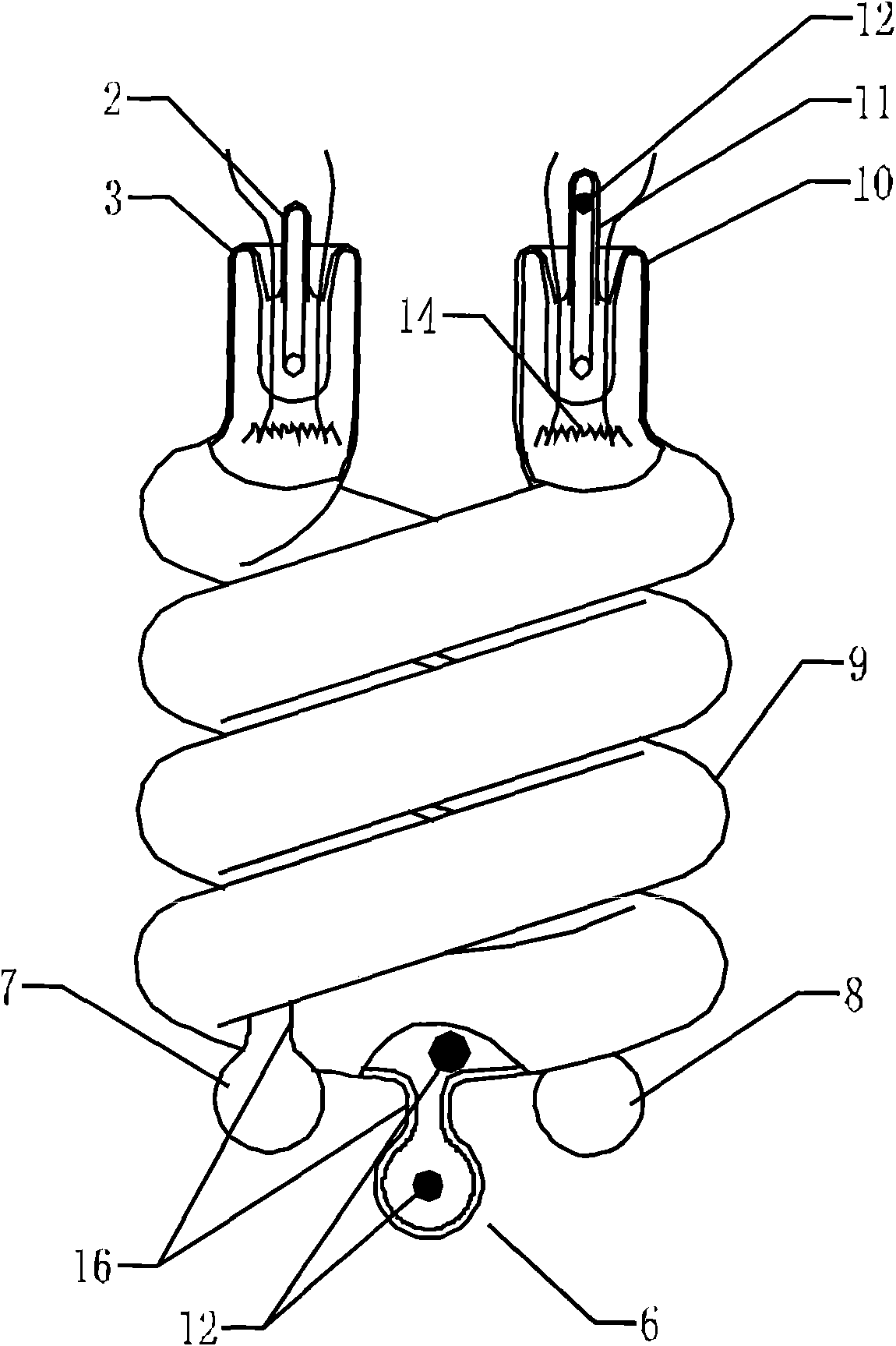
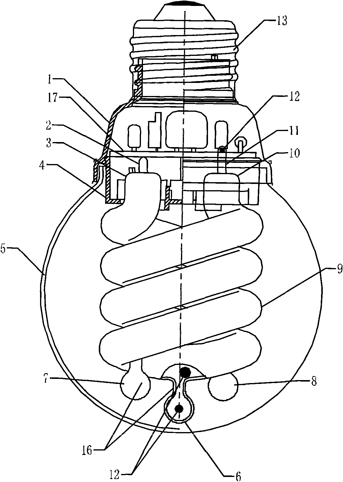
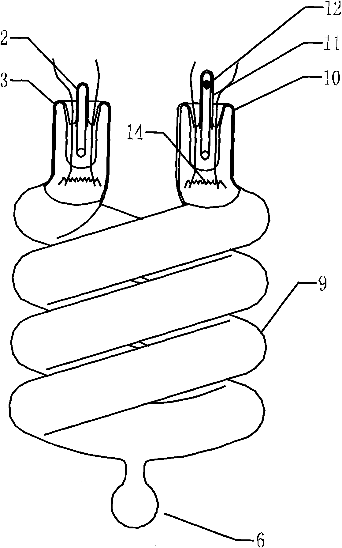
[0033] 1: Upper cover 10: Lamp foot

[0034] 2: Short exhaust pipe 62: Connecting pipe

[0035] 3: lamp pin 12: amalgam

[0036] 4: base 13: lamp head

[0037] 5: Shade 14: Filament

[0038] 6: Bubble part 61: Bubble

[0039] 7: Bubble relief 17: Ballast

[0040] 8: Slowing bubbles 9: Light emitting tube

[0041] 11: Long exhaust pipe

[0042] see figure 1 , figure 2, The lamp holder 13, the upper cover 1, the lampshade 5, the base 4, the ballast 17 fixed on the base 4 and the luminous tube 9 form an energy-saving lamp with a cover. In this embodiment, the luminous tube 9 is a special-shaped spiral fluorescent tube. The short exhaust pipe 2 on the la...


PUM


Abstract

The invention provides a fluorescence radiation lamp tube, which adopts liquid mercury or low temperature amalgam, one or more than one projecting bulb is disposed on the wall of the radiation lamp tube, a communicating tube is arranged between the projecting bulbs and the radiation tube for communicating the projecting bulbs with the radiation lamp tube, and the communicating tube is thinner than the projecting bulbs. Heat resistance is formed between a cavity of the lamp tube and the projecting bulbs, and each projecting bulb is thicker than the communicating tube relatively, then larger superficial area is offered for heat dissipation, and under the interaction of the two factors, temperature in the projecting bulbs can be properly adjusted to the ideal operating temperature of the liquid mercury or low temperature amalgam, so as to achieve the unimaginable effect, stable and ideal mercury vapor pressure can exist in the cavity of the radiation tube, and lighting effects of fast lighting and ideal luminous flux can be realized under the condition of matching a lampshade.

Description

technical field [0001] The invention relates to a fluorescent light tube, in particular to a special-shaped fluorescent light tube. Background technique [0002] Various shaded fluorescent lamps with similar shapes to incandescent lamps have obvious energy-saving effects compared with incandescent lamps, and are being more and more widely used in lighting in homes and public places. Previously, energy-saving lamps with shades used high-temperature amalgam. This kind of amalgam can only maintain the ideal mercury vapor pressure required by the fluorescent lamp at a relatively high operating temperature. After the lamp is lit, to make the position of the high-temperature amalgam reach the ideal operating temperature, it needs to go through a period of uneven heating delay time. In order to make the fluorescent light-emitting tube emit the ideal luminous flux. Of course, the use of auxiliary amalgam can shorten this period of time, but due to the limitations of various process...

Claims


Application Information

Patent Timeline
IPC IPC(8): H01J61/30H01J61/28
CPCH01J61/327H01J61/28
Inventor 胡忠浩吴钜军赵亚平钱震
Owner RAYWA LIGHTING & ELECTRICAL CORP
Why Eureka
Try Eureka