Method for manufacturing pressure-resistant plate

A manufacturing method and technology of pressure-resistant plates, applied in chemical instruments and methods, lamination, sheet/board, etc., can solve the problems of not being hard and solid enough, unable to discharge, and low production efficiency

Active Publication Date: 2010-07-14
龙廷实业股份有限公司
View PDF3 Cites 1 Cited by
  • Summary
  • Abstract
  • Description
  • Claims
  • Application Information

AI Technical Summary

Problems solved by technology

[0004] However, there are following defects in the above manufacturing process: see figure 1 and figure 2 , when the large-unit pressure-resistant body A is transported forward after the drying and shaping step, because the gluing operation is performed on the upper surface and the lower surface of the large-unit pressure-resistant body A synchronously, and then the large-unit pressure-resistant body A is When moving forward, it is gradually pulled and unfolded to an appropriate opening state, and then the top plate B and bottom plate C are attached to the upper and lower surfaces of the large unit pressure body A, and when passing through the pressure table, the pressure table is applied. The large unit pressure body A is tightly bonded between the top plate B and the bottom plate C, and then combined into a pressure plate
Due to the moisture contained in the glue, it must wait for a period of time to dry completely after bonding, and the production efficiency is low, because, if it is not completely dry, the large unit pressure body A itself will have residual moisture and appear wet and soft. In this way, it will not be able to withstand the heavy pressure and will be crushed. This is because the pressure-resistant body A of the large unit itself is not hard and solid enough.
In addition, the top plate B and the bottom plate C are in close contact with the pressure-resistant body A of the large unit at the same time, so that the water in the glue cannot be discharged in a timely manner, but is covered in the honeycomb holes and cannot be discharged (see figure 2 ), so that the final pressure plate itself is not hard enough due to residual moisture

Method used


Image

  • Method for manufacturing pressure-resistant plate
  • Method for manufacturing pressure-resistant plate
  • Method for manufacturing pressure-resistant plate

Examples


Embodiment Construction

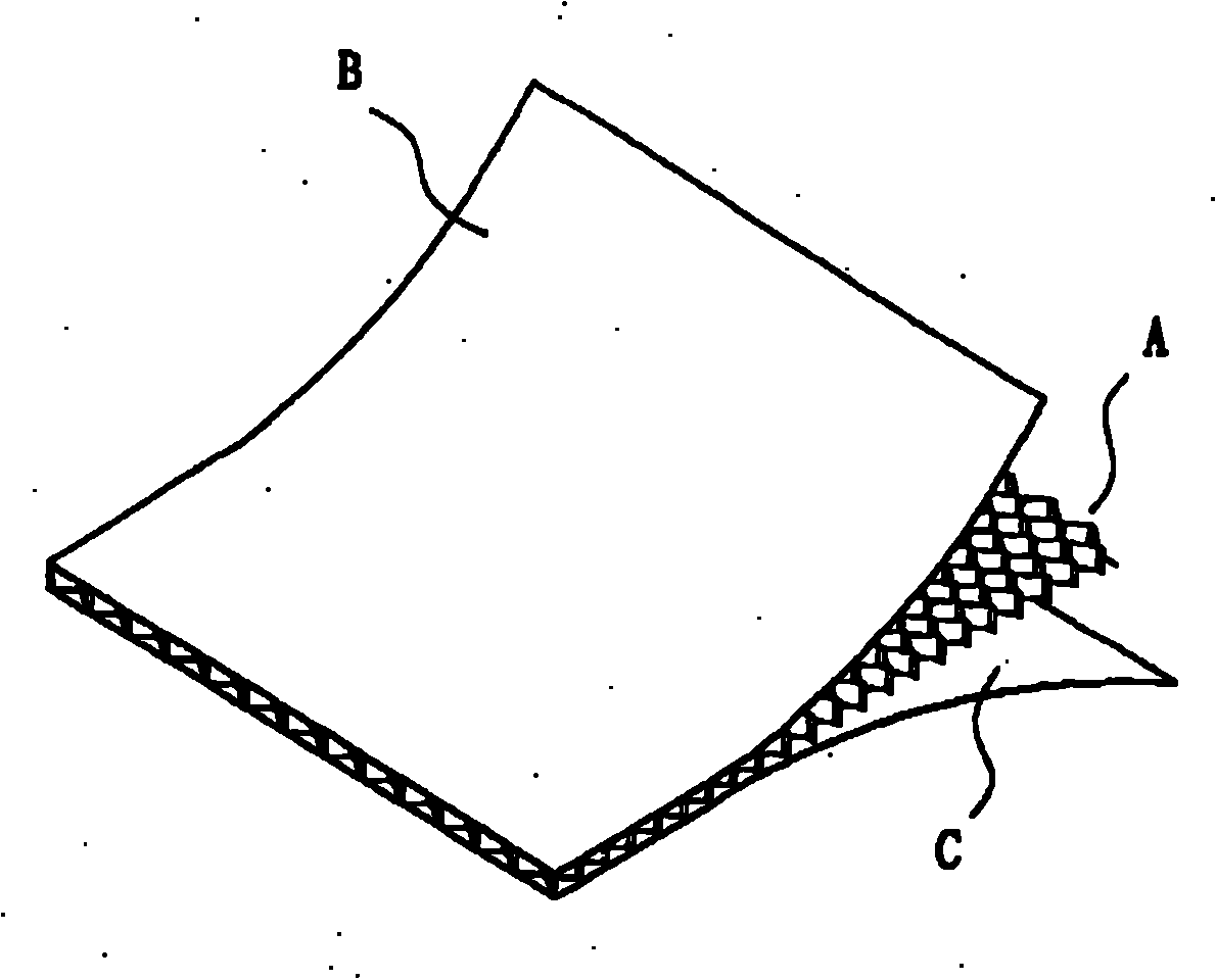
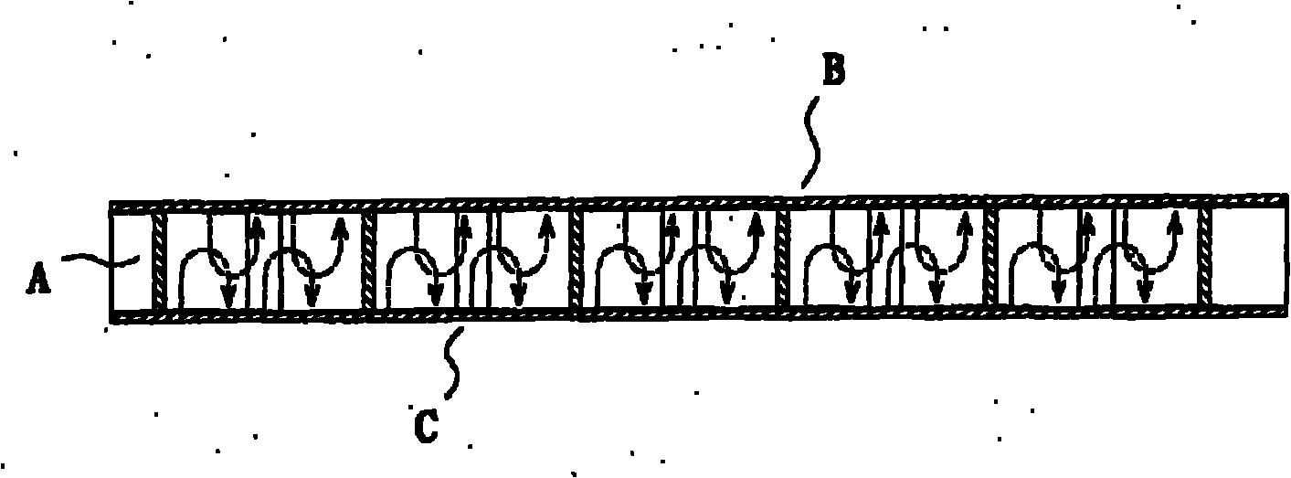
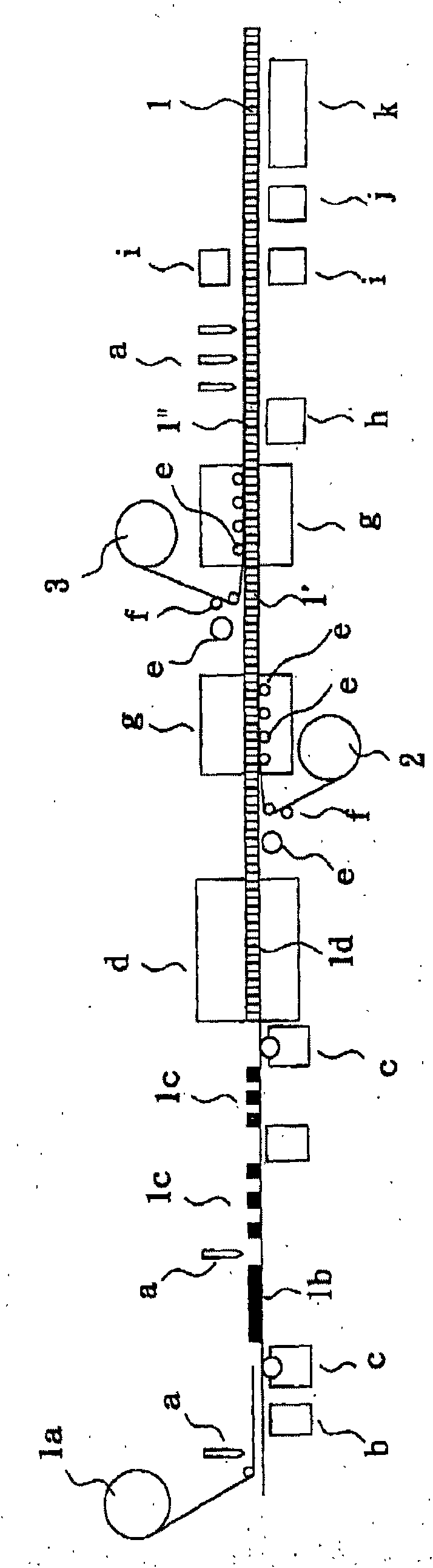
[0021] see image 3 , according to an embodiment of the inventive concept, there are the following steps, specifically:

[0022] Substrate cutting

[0023] Cut a roll of recycled paper substrate 1a into a predetermined number of small-area substrates 1b of appropriate size and size by a paper cutter a in sequence as required, and then use a paper feeder b to cut each small area. The substrates 1b are sent to the gluing machine c one by one for gluing operation. After gluing, the front and rear sheets are laminated and bonded to each other in sequence. The parts to be pasted are completely different, that is, after the small-area substrate 1b is pasted, different pasting parts will appear in the order of odd-numbered sheets and even-numbered sheets.

[0024] Small unit withstand voltage single formation

[0025] According to the required design height of the pressure-resistant body, the small-area base material 1b that has been bonded as a whole is subdivided into a predeter...


PUM


Abstract

The invention discloses a method for manufacturing a pressure-resistant plate. The method comprises the following steps of: single-sided molding, namely coating an adhesive on the lower surface of a large-area pressure-resistant body, and pressing and positioning the lower surface of the pressure-resistant body onto a bottom plate and drying the adhesive; double-sided molding, namely coating the adhesive on the upper surface of the large-area pressure-resistant body, and pressing and positioning the upper surface onto a top plate; trimming, namely trimming after the double-sided molding; and cutting, namely cutting required pressure-resistant plates of each predetermined length. In the processes of adhering the top plate and the bottom plate to the upper surface and the lower surface of the large-area pressure-resistant body from the lower surface to the upper surface respectively and orderly, the contained moisture can be rapidly evaporated and discharged and the total drying time is shortened, so that the manufactured pressure-resistant plate has stronger and harder structure strengthening effect after being dried completely and the capacity of bearing an external force is improved.

Description

technical field [0001] The invention relates to a manufacturing method for combining a honeycomb board core with other cardboards to form a pressure-resistant board. Background technique [0002] The pressure-resistant plate, also known as the honeycomb plate, is composed of a pressure-resistant body and a plate attached to the upper and lower surfaces of the pressure-resistant body. It is usually used for the packaging of fragile items, and acts as a buffer against external forces. [0003] The conventional pressure-resistant board manufacturing method usually has the following steps: a cutting step: cutting a base material composed of a roll of recycled paper into a predetermined number of small-area base materials with appropriate specifications and sizes in sequence as required; a pasting step. : Then use a paper feeder to send each small-area substrate to the gluing machine one by one for gluing operation. After gluing, the front and back sheets are laminated and bonde...

Claims


Application Information

Patent Timeline
Patent Type & Authority Applications(China)
IPC IPC(8): B32B37/12B32B38/04B32B38/00F16S1/10
Inventor 洪志修
Owner 龙廷实业股份有限公司
Why Eureka
Try Eureka