
Unpowered sludge dehydration device

A sludge dewatering and power technology, applied in the direction of dewatering/drying/concentrating sludge treatment, can solve the problems of large volume, high mechanical maintenance cost and high cost, and achieve the effect of small volume, good dewatering effect and simple structure

Inactive Publication Date: 2010-07-14
无锡光初科技服务有限公司
View PDF5 Cites 4 Cited by
  • Summary
  • Abstract
  • Description
  • Claims
  • Application Information

AI Technical Summary

Problems solved by technology

[0002] Sewage treatment will produce sludge, and most of the sludge is activated sludge with a particularly high water content, most of which are organic matter, and also contain toxic substances, heavy metals, phosphorus, ammonia, nitrogen and other substances. If the sludge is not dehydrated, it will be It brings troubles to the comprehensive treatment of sludge transportation, packaging, deep processing, power generation, incineration, etc. Conventional (50%) sludge treatment needs to obtain relatively dry sludge, which must be buried, filtered, centrifugally separated, and vacuum squeezed Separation, heating separation and other methods need to consume a lot of power energy and heat energy. At the same time, all sludge dewatering equipment is bulky, expensive, requires high mechanical maintenance costs, and requires a lot of labor to operate.
Calculated according to the moisture content of 80%, my country will produce 30 million tons of sludge from 2009 to 2010. If the above traditional methods are used to deal with it, a lot of money and energy will be wasted.

Method used


Image

  • Unpowered sludge dehydration device
  • Unpowered sludge dehydration device
  • Unpowered sludge dehydration device

Examples


Embodiment Construction

[0012] The present invention will be further described below in conjunction with specific drawings and embodiments.

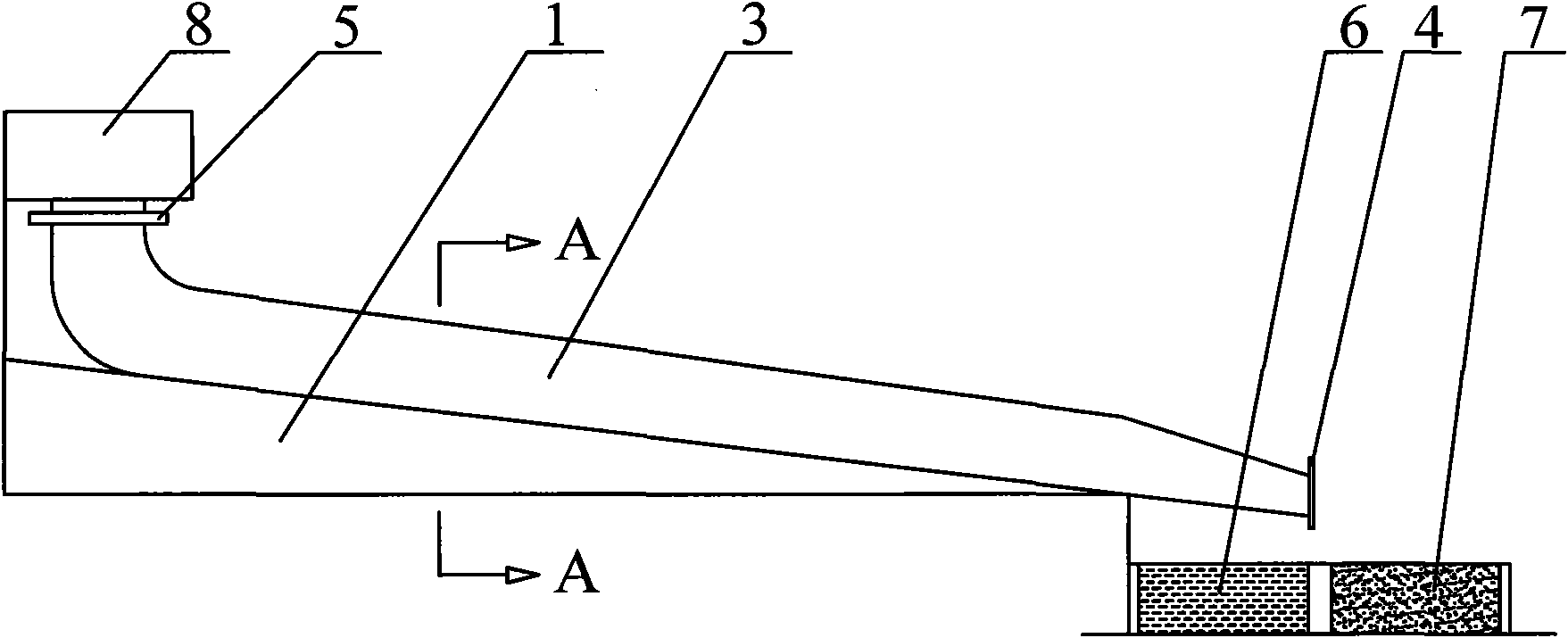
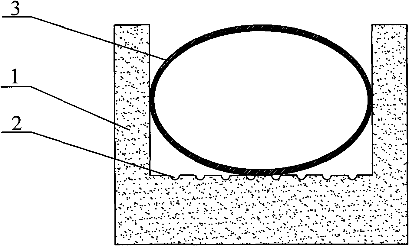
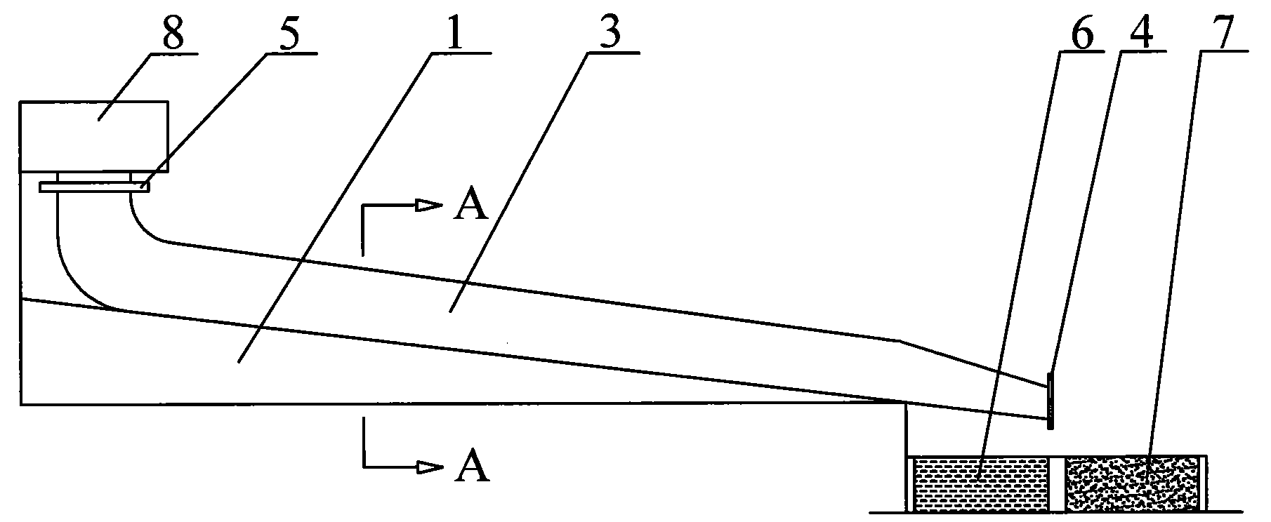
[0013] As shown in the figure: the unpowered sludge dewatering device includes a liquid flow tank 2 set on the upper surface of the bottom of the dewatering tank 1. The upper surface of the tank bottom of the dewatering tank 1 is inclined to the horizontal plane. Dehydration woven bag 3 is placed on the top surface of the tank bottom of dehydration tank 1, the length direction of dehydration woven bag 3 is consistent with the length direction of dehydration tank 1, the outlet end of dehydration woven bag 3 extends out of dehydration tank 1, and the dehydration weaving The inlet height of the bag 3 is higher than the outlet height of the dehydration woven bag 3, and the inlet end of the dehydration woven bag 3 is arranged above the high end of the dehydration tank platform 1, and a tie belt body 4 is arranged at the outlet of the dehydration woven bag 3. A water...


PUM


Abstract

The invention relates to an unpowered sludge dehydration device, comprising a fluid bath arranged on the upper surface of the tank bottom of a dehydration tank; wherein the upper surface of the tank bottom of the dehydration tank is obliquely arranged with the horizontal plane, a dehydration woven bag is arranged on the upper surface of the tank body of the dehydration tank, the length direction of the dehydration woven bag is the same as the length direction of the dehydration tank, an outlet end of the dehydration woven bag stretches out of the dehydration tank and the inlet height of the dehydration woven bag is higher than the outlet height of the dehydration woven bag; the inlet end of the dehydration woven bag is arranged above a high end of the dehydration tank, a tying belt is arranged at the outlet of the dehydration woven bag and a water storage tank and a slag storage tank are arranged at the outside of a low end of the dehydration tank; wherein the distance between the water storage tank and the low end of the dehydration tank is smaller than the distance between the slag storage tank and the low end of the dehydration tank. After being installed, the unpowered sludge dehydration device can automatically carry out dehydration without external power, features good dehydration effect, simple structure, small volume, low manufacturing cost and conservation of massive funds and energy.

Description

technical field [0001] The invention relates to an environmental protection device, in particular to an unpowered sludge dewatering device. Background technique [0002] Sewage treatment will produce sludge, and most of the sludge is activated sludge with a particularly high water content, most of which are organic matter, and also contain toxic substances, heavy metals, phosphorus, ammonia, nitrogen and other substances. If the sludge is not dehydrated, it will be It brings troubles to the comprehensive treatment of sludge transportation, packaging, deep processing, power generation, incineration, etc. Conventional (50%) sludge treatment needs to obtain relatively dry sludge, which must be buried, filtered, centrifugally separated, and vacuum squeezed Separation, heating and separation methods consume a lot of power energy and heat energy. At the same time, all sludge dewatering equipment is bulky, expensive, requires high mechanical maintenance costs, and requires a lot of...

Claims


Application Information

Patent Timeline
IPC IPC(8): C02F11/12
Inventor 强光初
Owner 无锡光初科技服务有限公司
Learn More