
Waste rolling oil regeneration device

A regeneration device and rolling oil technology, applied in the direction of molecular distillation, lubricating composition, etc., can solve the problems of wasting resources, polluting the environment, and increasing the viscosity of rolling oil, and achieve reasonable structural design, high purity, and high regeneration efficiency Effect

Inactive Publication Date: 2010-07-14
王树波 +1
View PDF2 Cites 11 Cited by
  • Summary
  • Abstract
  • Description
  • Claims
  • Application Information

AI Technical Summary

Problems solved by technology

[0002] The production of high-quality, high-grade and high-value-added aluminum strip and foil is the pursuit of the development of aluminum enterprises. The quality control of aluminum foil rolling oil is particularly important in the use process, because the use process is inevitably affected by mechanical oil, hydraulic oil, grease, etc. And aluminum metal powder impurities "pollution", replacing the waste rolling oil off the production line as fuel oil incineration, can not be recycled, the first waste of resources, the second increases the cost of the enterprise, and the third is when the fuel oil incineration pollutes the environment
[0003] Aluminum strip and foil rolling oil will inevitably be mixed with a small amount of heavy oil and mechanical impurities during the working process. These impurities will increase the viscosity of the rolling oil and affect the cooling and lubrication effects. The carbon chains of these polymer heavy oil components are continuous It is easy to break at high temperature, causing symptoms such as yellow spots on the aluminum strip and foil. Aluminum rolling companies will consider replacing with new oil immediately

Method used


Image

  • Waste rolling oil regeneration device
  • Waste rolling oil regeneration device

Examples


Embodiment 1

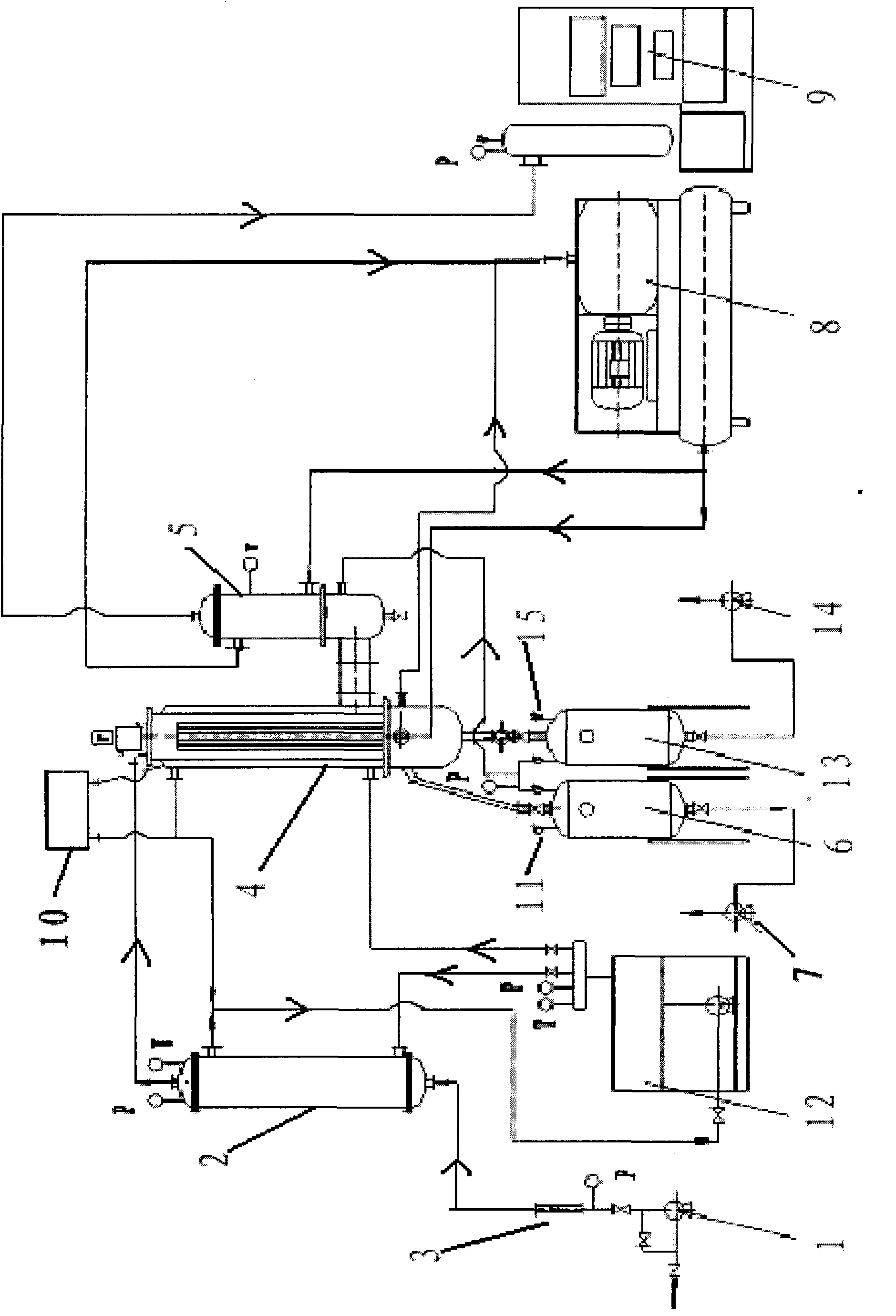
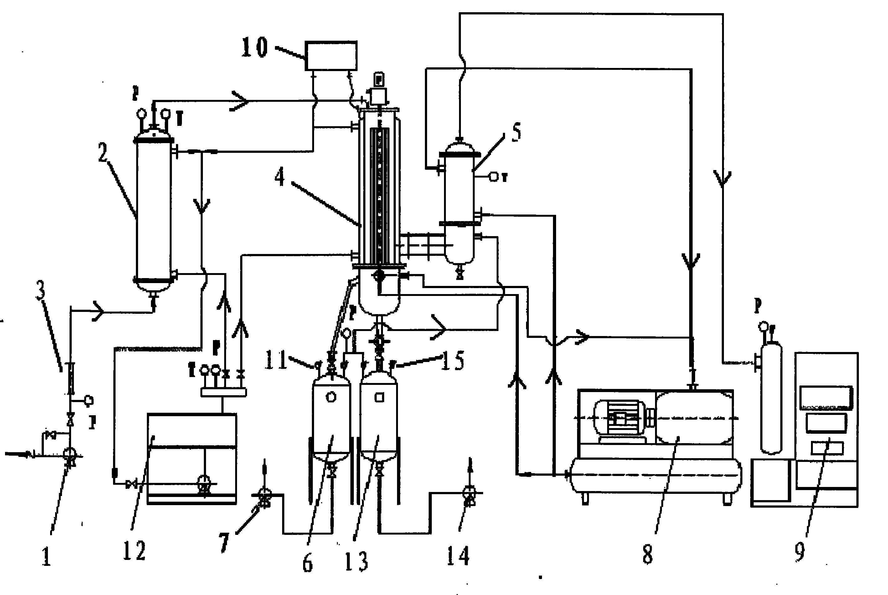
[0016] The waste rolling oil regenerating device of this embodiment includes an oil inlet pump 1 for supplying waste rolling oil. The oil inlet pump 1 is connected with a heat exchanger 2 for heating the waste rolling oil. A flow meter 3 for measuring waste rolling oil is arranged between them, and the output end of the heat exchanger 2 is connected with a thin-film distiller 4 for separating rolling oil and heavy oil, and the input ends of the heat exchanger 2 and the thin-film distiller 4 The heat conduction oil furnace 12 is connected in circulation, and the thin film distiller 4 is connected with a condenser 5 for collecting gas rolling oil, and the condenser 5 is connected with a vacuum degree used to meet the requirements of the thin film evaporator 4, so that the rolling oil evaporates below the flash point The vacuum unit 9 of the thin film distiller 4 is connected with a heavy oil tank 6 for collecting unevaporated heavy oil and a product oil tank 13 for collecting fin...


PUM


Abstract

The invention relates to a waste rolling oil regeneration device belonging to the technical field of regeneration device structures. The waste rolling oil regeneration device comprises an oil feeding pump which is connected with a heat exchanger; a flowmeter for metering waste rolling oil is arranged between the oil feeding pump and the heat exchanger; the output end of the heat exchanger is communicated with a thin film distiller for separating rolling oil from heavy oil; the input ends of the heat exchanger and the thin film distiller are circularly communicated with a heat conducting oil furnace; the thin film distiller is connected with a condenser for collecting gas rolling oil; the condenser is connected with a vacuum unit for meeting the vacuum degree required by the thin film distiller and evaporating the rolling oil below a flash point; and the lower end of the thin film distiller is connected with a heavy oil tank for collecting heavy oil which is not evaporated and a finished product oil tank for collecting finished oil. The invention has reasonable structural design and fully protects base oil components of the rolling oil and addictive components from being damaged; and meanwhile, the regeneration efficiency of the waste rolling oil is excessively high and the purity of the regenerated rolling oil is excessively high.

Description

technical field [0001] The invention relates to a regeneration device for waste rolling oil, which belongs to the technical field of regeneration device structure. Background technique [0002] The production of high-quality, high-grade and high-value-added aluminum strip and foil is the pursuit of the development of aluminum enterprises. The quality control of aluminum foil rolling oil is particularly important in the use process, because the use process is inevitably affected by mechanical oil, hydraulic oil, grease, etc. And aluminum metal powder impurities "pollution", replacing the waste rolling oil off the production line as fuel oil incineration, can not be recycled, the first waste of resources, the second increases the cost of enterprises, and the third is when fuel oil incineration pollutes the environment. [0003] Aluminum strip and foil rolling oil will inevitably be mixed with a small amount of heavy oil and mechanical impurities during the working process. The...

Claims


Application Information

Patent Timeline
Patent Type & Authority Applications(China)
IPC IPC(8): C10M175/00C10M175/02B01D3/12
Inventor 董海生王树波
Owner 王树波
Learn More