Connection structure of motion guide rod and rotor and electronic expansion valve

A technology of connecting structure and guide rod, applied in valve details, valve device, engine components, etc., can solve the problems of rotor thermal influence, failure, magnetic intensity change of rotor surface, etc., and achieve good connection quality, accurate positioning, and travel limit. Bit accurate effects

Active Publication Date: 2010-07-14
ZHEJIANG DUNAN HETIAN METAL CO LTD
View PDF4 Cites 6 Cited by
  • Summary
  • Abstract
  • Description
  • Claims
  • Application Information

AI Technical Summary

Problems solved by technology

[0006] The purpose of the present invention is to provide a connection structure between the guide rod and the rotor, so as to solve the problems of the welding of the guide rod and the rotor in the prior art, which will have a thermal impact on the rotor, and directly cause the magnetic intensity of the rotor surface to change or even fail.

Method used


Image

  • Connection structure of motion guide rod and rotor and electronic expansion valve
  • Connection structure of motion guide rod and rotor and electronic expansion valve
  • Connection structure of motion guide rod and rotor and electronic expansion valve

Examples


Embodiment Construction

[0041] The present invention will be described in detail below with reference to the accompanying drawings and in combination with embodiments.

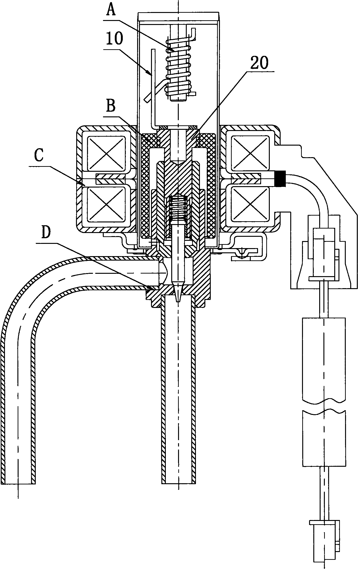
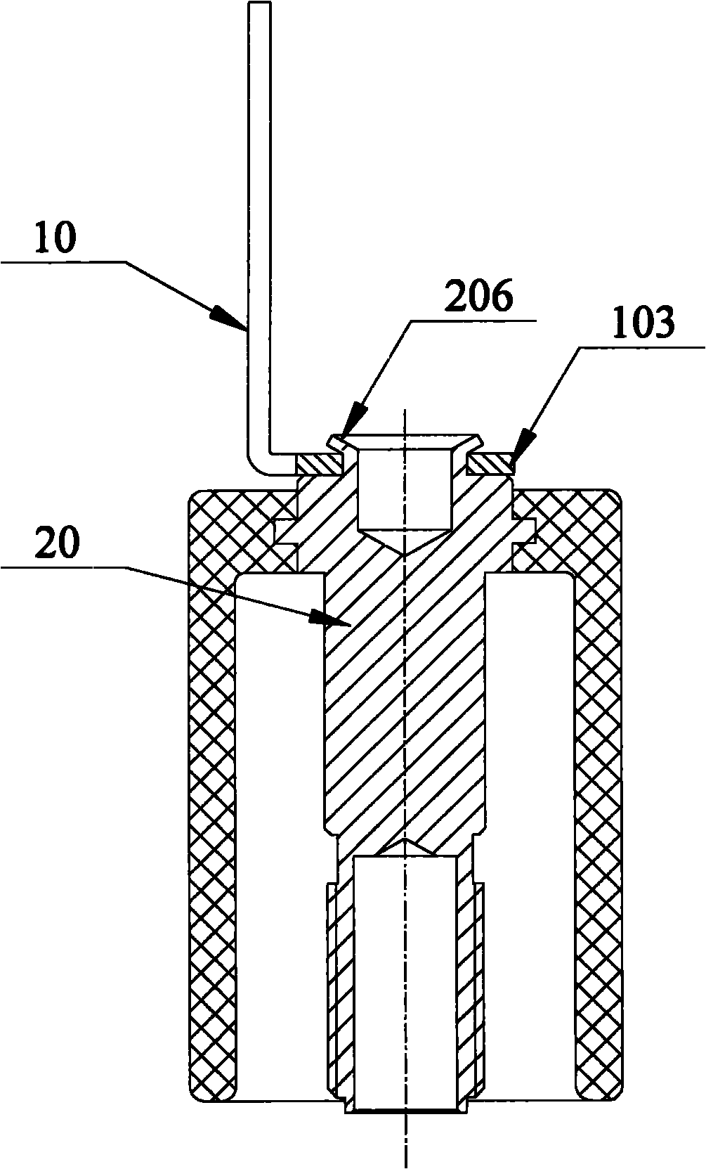
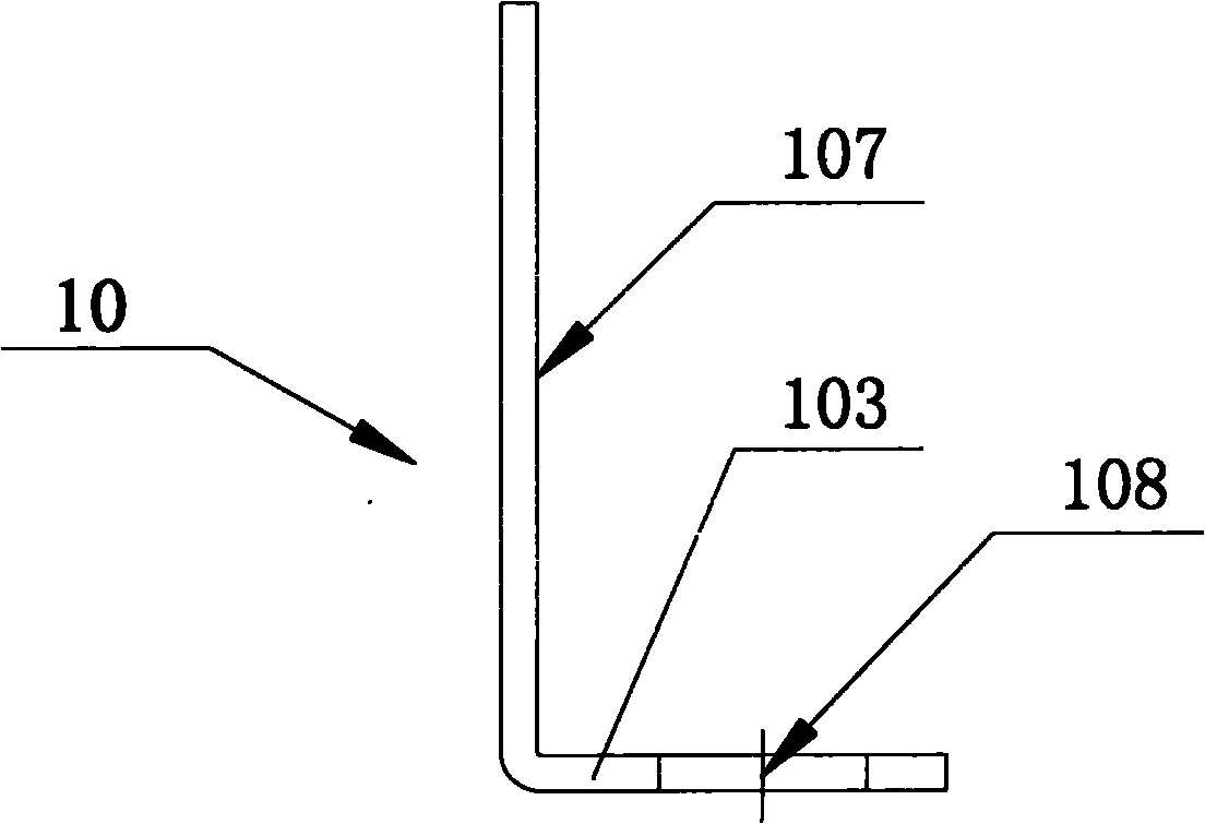
[0042] figure 2 The connection structure between the guide rod and the rotor according to the first embodiment of the present invention is schematically shown in cross-sectional structure. The connection structure between the guide rod and the rotor includes: a guide rod 10 and a rotor screw 20, wherein, as image 3 As shown, the section of the guide rod 10 is L-shaped, such as Figure 4 to Figure 6 As shown, the guide rod 10 includes: a vertical guide rod vertical section 107, a connecting section 103 that is horizontally arranged and connected with the guide rod vertical section 107, and the connecting section 103 can be, for example, a circle with a positioning hole 108. The annular plate can also be a rectangular plate, and the upper end of the rotor screw 20 is riveted with the connecting section 103 , for example, the upper ...


PUM


Abstract

The invention provides a connection structure of a motion guide rod and a rotor, comprising the motion guide rod and a rotor screw, wherein the section of the motion guide rod is in an L shape; the motion guide rod comprises a motion guide rod vertical segment and a connection segment, wherein the motion guide rod vertical segment is vertically arranged, and the connection segment is horizontally arranged and is connected with the motion guide rod vertical segment; and the upper end of the rotor screw is riveted with the connection segment. The invention also provides an electronic expansion valve comprising a limiter assembly A, a rotor assembly B, a stator coil C and a valve body assembly D, wherein the limiter assembly A comprises the connection structure of the motion guide rod and the rotor. The invention solves the problem that the magnetic strength of the surface of the rotor is changed and even loses efficacy directly because the motion guide rod and the rotor are mutually welded to generate heat influence on the rotor in the prior art, thereby achieving the effects of good connection quality, simple and convenient connection process, stable connection, convenient processing, accurate stroke limit of the limiter assembly A and accurate positioning of the electronic expansion valve.

Description

technical field [0001] The invention relates to the refrigeration field, and more specifically, to a connection structure between a guide rod and a rotor and an electronic expansion valve. Background technique [0002] In the refrigeration system, the electronic expansion valve is used to adjust the flow of refrigerant in the system and is an indispensable component of the refrigeration system. The electronic expansion valve is composed of a valve body and a coil. The power provided by the coil can control the action of the relevant parts in the valve body to open or close the valve port and adjust the opening of the valve port, thereby realizing the control of the refrigerant. [0003] The stroke of the magnetic rotor inside the electronic expansion valve is controlled by a set of limit structures. Most of the current limit structures are composed of a guide rod and a limit spring, such as figure 1 As shown, the existing electronic expansion valve includes: a stopper assem...

Claims


Application Information

Patent Timeline
Patent Type & Authority Applications(China)
IPC IPC(8): F16K31/06F25B41/06
CPCY02B30/72Y02B30/70
Inventor 黄长金王冠军
Owner ZHEJIANG DUNAN HETIAN METAL CO LTD
Why Eureka
Try Eureka