Concentrated-winding multi-segment permanent magnet synchronous linear motor

A permanent magnet synchronous linear and concentrated winding technology, applied in the shape/style/structure of winding conductors, electrical components, electromechanical devices, etc., can solve problems such as low system operation efficiency, reduce losses, reduce cogging positioning force and edge positioning force, the effect of reducing energy consumption

Inactive Publication Date: 2010-07-14
HARBIN INST OF TECH
View PDF8 Cites 19 Cited by
  • Summary
  • Abstract
  • Description
  • Claims
  • Application Information

AI Technical Summary

Problems solved by technology

[0004] The purpose of the present invention is to provide a concentrated winding segmented permanent magnet synchronous linear motor to solve the problem that the stator windings of the existing long primary moving magnet steel type permanent magnet synchronous linear motor are energized at the same time and the system operation efficiency is low.

Method used


Image

  • Concentrated-winding multi-segment permanent magnet synchronous linear motor
  • Concentrated-winding multi-segment permanent magnet synchronous linear motor
  • Concentrated-winding multi-segment permanent magnet synchronous linear motor

Examples


specific Embodiment approach 1

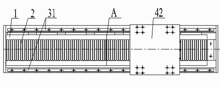
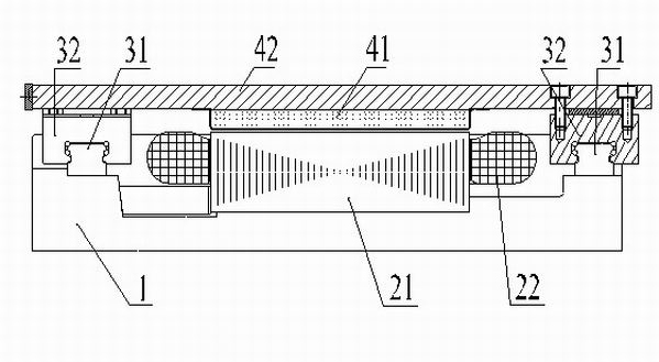
[0010] Specific implementation mode one: the following combination Figure 1 to Figure 4 Describe this embodiment, this embodiment includes machine base 1, armature 2, a pair of guide rails 31, a pair of sliders 32, many pairs of permanent magnets 41 and mover body 42,

[0011] The armature 2 is arranged in the middle of the upper surface of the base 1, and a pair of guide rails 31 are arranged on both sides of the armature 2 on the upper surface of the base 1, and a pair of guide rails 31 are slidably connected with a pair of sliders 32. The block 32 is fixedly connected with the mover body 42, and a plurality of pairs of permanent magnets 41 are arranged in a row and multiple columns on the inner surface of the mover body 42 along the movement direction, and there is an air gap between the permanent magnets 41 and the armature 2;

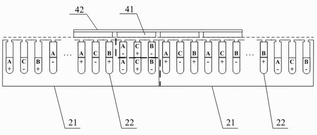
[0012] The armature 2 is composed of a multi-section armature core 21 and a multi-section armature winding 22. The multi-section armature core 21...

specific Embodiment approach 2

[0014] Specific implementation mode two: the following combination Figure 6 and Figure 7 Describe this embodiment, the difference between this embodiment and Embodiment 1 is that the permanent magnet 41 is a rectangular permanent magnet, the magnetization direction of the rectangular permanent magnet is perpendicular to the mover body 42, and the magnetization direction of the adjacent rectangular permanent magnets is opposite; The width L of the rectangular permanent magnet m The value range is L m =(0.75~0.9)τ p , where τ p is the pole pitch of the rectangular permanent magnet. Other components and connections are the same as those in Embodiment 1.

[0015] In this embodiment, the permanent magnet 41 adopts a rectangular permanent magnet, and grooves are arranged on the surface of the moving sub-body 42 , the rectangular permanent magnet is surface-attached in the groove of the moving sub-body 42 , and N and S poles are arranged alternately. The width of the permanen...

specific Embodiment approach 3

[0016] Specific implementation mode three: the following combination Figure 8 and Figure 9 Describe this embodiment. The difference between this embodiment and Embodiment 1 or 2 is that the permanent magnet 41 is a rectangular permanent magnet, and the surface of the permanent magnet 41 on the side of the air gap is a convex arc surface. The permanent magnets 41 are magnetized radially, and the magnetization directions of adjacent permanent magnets 41 are opposite. Other compositions and connections are the same as those in the first or second embodiment.

[0017] The permanent magnet 41 in this embodiment adopts a convex arc surface structure, which is attached to the moving body 42, and the N and S poles are arranged alternately. This structure is conducive to the formation of a sinusoidal magnetic field in the air gap, effectively reducing the motor teeth The positioning force and thrust fluctuation of the groove.


PUM


Abstract

The invention discloses a concentrated-winding multi-segment permanent magnet synchronous linear motor, which belongs to the technical field of liner motors and solves the problem of low system operation efficiency of the traditional primary dynamic magnetic steel type permanent magnet synchronous linear motor of which the rotor windings are electrified at the same time. In the concentrated-winding multi-segment permanent magnet synchronous linear motor, an armature is arranged in the middle of the upper surface of a machine seat; a pair of guide rails is arranged on two sides of the armature on the upper surface of the machine seat; the pair of the guide rails are in sliding fit connection with a pair of sliding blocks which are fixedly connected with a rotor body; a plurality of pairs of permanent magnets are arranged on the inner surface of the rotor body along a motion direction in one row and a plurality of columns; air gaps are reserved between the permanent magnets and the armature; a plurality of segments of armature cores are sequentially and closely connected in the motion direction of the rotor body; the armature cores adopt a tooth slot structure; a segment of armature winding is embedded in the tooth slot of each segment of armature core; each segment of armature winding is a concentrated winding; and two adjacent segments of armature windings are overlapped to be embedded on the end part of each segment of armature core, wherein the length of the overlapped area is equal to the pitch, which is 1, of the windings. The motor is applicable to heavy-load propulsion systems.

Description

technical field [0001] The invention relates to a concentrated winding segmented permanent magnet synchronous linear motor, which belongs to the technical field of linear motors. Background technique [0002] Linear motor is a new type of drive device that directly generates linear motion. It converts electrical energy into mechanical energy for linear motion. Compared with non-linear motors, it eliminates the intermediate transmission links such as screw and rack and pinion. It has simple structure, With the advantages of fast response speed and high precision, it improves the efficiency of the system while reducing the manufacturing cost. [0003] Flat permanent magnet synchronous linear motors can be divided into two types according to different moving parts: moving armature type and moving magnet steel type. The former's mover is composed of an armature, and multiple permanent magnets constitute the stator of the motor. For permanent magnet synchronous linear motors wi...

Claims


Application Information

Patent Timeline
Patent Type & Authority Applications(China)
IPC IPC(8): H02K41/03H02K3/12
Inventor 李立毅马明娜寇宝泉李鹏
Owner HARBIN INST OF TECH
Why Eureka
Try Eureka