Process for producing a motion sensor

A motion sensor and injection molding machine technology, which is applied to the assembly/disassembly of instruments, measuring instrument components, and contact pieces, can solve the problems of increasing manufacturing costs and manufacturing costs, reduce floor space requirements, facilitate costs, and avoid The effect of pressure load

Inactive Publication Date: 2011-07-06
ROBERT BOSCH GMBH
View PDF1 Cites 0 Cited by
  • Summary
  • Abstract
  • Description
  • Claims
  • Application Information

AI Technical Summary

Problems solved by technology

However, the conversion of parts and auxiliary molds is limited by additional processing steps and special equipment, thereby increasing manufacturing expenses and manufacturing costs

Method used


Image

  • Process for producing a motion sensor
  • Process for producing a motion sensor
  • Process for producing a motion sensor

Examples


Embodiment Construction

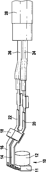
[0015] figure 1 An electric component 10 , which is injection-moulded with a thermoplastic material according to the proposed method, is shown for a rotational speed sensor for detecting the rotation of a vehicle wheel. The electrical assembly contains an IC functional block 11 with an integrated circuit for supplying measurement signals and outputting measured values. The magnetic field for generating the measurement signal is provided by a cylindrical permanent magnet 12 which is arranged directly adjacent to the IC functional block 11 . The two printed conductor strips 14 and 16 of the integrated circuit 11 are bridged via a capacitor 18 to eliminate signal peaks and are connected via crimped connections (crimping) 20 and 22 to the connecting conductors 24 and 26 of a cable 28 whose Together with the leads 24 and 26, the capacitor 18, the permanent magnet 12 and the integrated circuit 11, the front end is injection-molded with plastic to form a finished motion sensor whose...


PUM


Abstract

The invention relates to a process for producing a motion sensor, in particular a rotational speed sensor for the rotation of a wheel of a motor vehicle. In this case, an electrical assembly (10) having an integrated circuit (IC; 11) and a connection cable (28) is encapsulated with plastic by means of injection moulding in that, in a first injection process, the assembly (10) is supported by means of a fixing insert (42) in the injection moulding machine (30) and is at least partially encapsulated with plastic in the region remote from the fixing insert (42). The fixing insert (42) is then removed and replaced by a second core (44) for the final encapsulation (58), and then the remaining encapsulation (60) of the assembly (10) and/or of the connection cable (28) is injected in a second injection process to form the final contour.

Description

technical field [0001] The invention relates to a method for producing a motion sensor. Background technique [0002] Known from DE 10 2004 033 284 A1 is a method and a device for producing plastic castings of electrical components of motion sensors and their connecting cables, wherein these components are positioned and assembled in a reusable auxiliary mold that can be assembled in an injection mold orientation. The electrical components and connecting cables are connected to each other by welding or soldering in an auxiliary mold and subsequently encapsulated in plastic in the injection mold, from which the parts are removed before their final injection molding and placed in another injection mold for final molding injection molding. This enables direct injection molding of these components without additional supports remaining in the potting compound, while maintaining the predetermined position of the components to be injection molded. Additional holders for componen...

Claims


Application Information

Patent Timeline
Patent Type & Authority Patents(China)
IPC IPC(8): G01P1/02B29C45/16B29C45/33G01D11/24H01R43/02H01R43/24
CPCB29C45/1618G01D11/245B29L2031/3061B29C45/33B29L2031/3462B29C45/14639B29C45/1671B29C45/162G01P1/026
Inventor G・韦里克R・比肖夫S・舒尔泽
Owner ROBERT BOSCH GMBH
Why Eureka
Try Eureka