
Equipment for loose body optical fiber prefabricated rod integral sintering desaeration and method thereof

A technology of optical fiber preform and loose body, which is applied in the field of equipment where vitrification and degassing are carried out simultaneously. It can solve the problems of residual bubbles in optical fiber preform, achieve the effects of shortening the production cycle, high pass rate, and reducing equipment investment

Active Publication Date: 2010-07-21
ZHONGTIAN TECH ADVANCED MATERIALS CO LTD +2
View PDF5 Cites 36 Cited by
  • Summary
  • Abstract
  • Description
  • Claims
  • Application Information

AI Technical Summary

Problems solved by technology

[0016] The object of the present invention is to provide a device and method for integrated sintering and degassing of a loose optical fiber preform in view of the above disadvantages. The second is to integrate the degassing process into the vitrification process of the optical fiber preform, without additional equipment and procedures; the third is to save a lot of helium compared with the existing sintering method

Method used


Image

  • Equipment for loose body optical fiber prefabricated rod integral sintering desaeration and method thereof
  • Equipment for loose body optical fiber prefabricated rod integral sintering desaeration and method thereof
  • Equipment for loose body optical fiber prefabricated rod integral sintering desaeration and method thereof

Examples


Embodiment 1

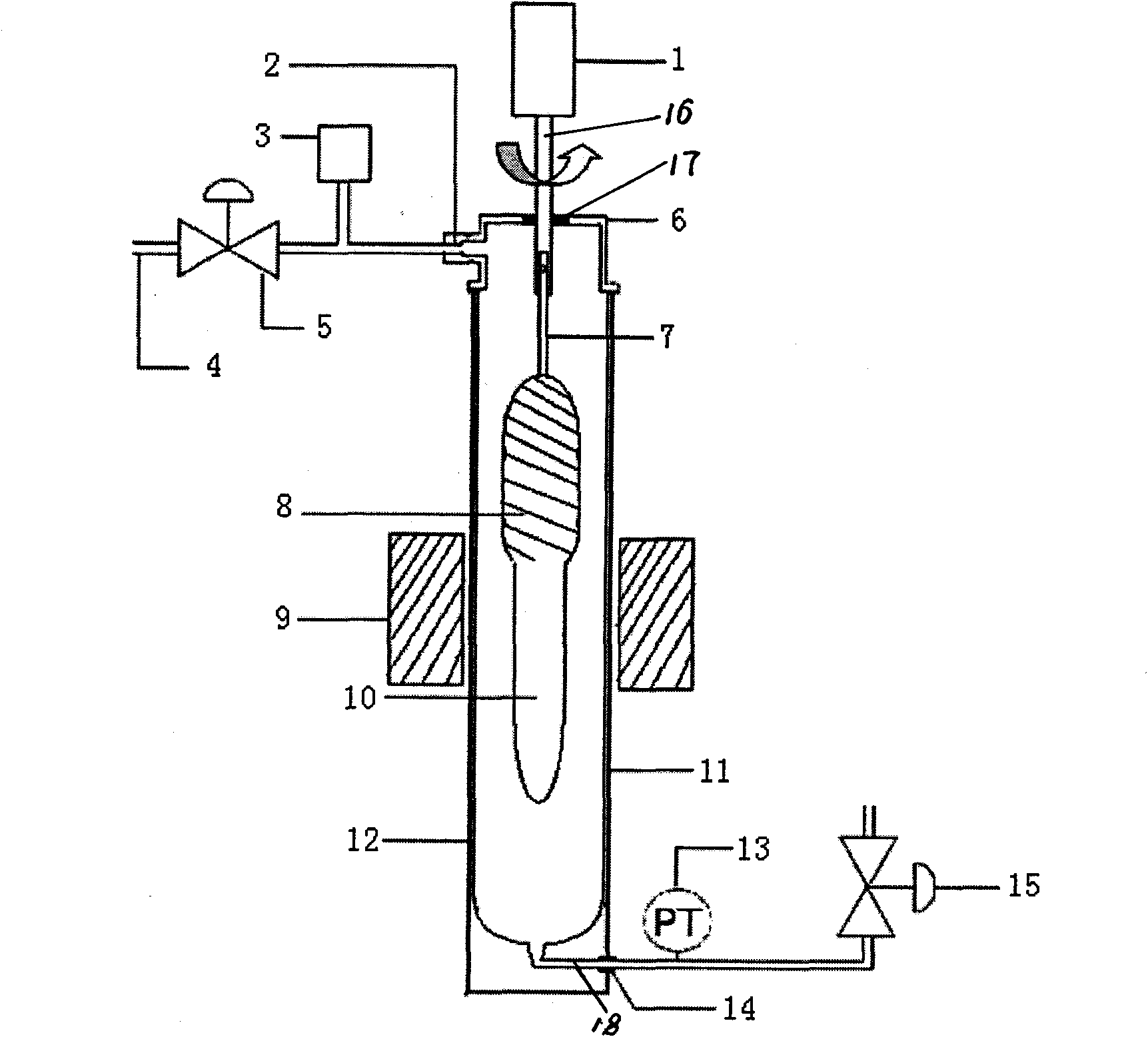
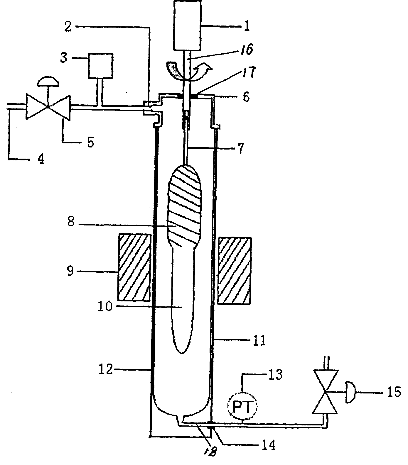
[0053] Embodiment 1. The temperature of the sintering furnace 9 was raised to 1150° C., and the chlorine gas pneumatic valve was opened to feed chlorine gas into the sintering furnace, and the flow rate of the chlorine gas was controlled at 0.8 L / min. Turn on the lowering rod system, control the descending speed of the powder preform at 5 mm / min, and control the rotation speed at 6 rpm. After the rod of the powder preform arrives at the hot zone 9 of the sintering furnace, the dehydration is completed, the falling of the powder preform is stopped, and the chlorine gas is turned off. The temperature of the sintering furnace 6 was raised to 1400°C, and helium gas was introduced into the sintering furnace 9, and the flow rate was set at 6 L / min. After 15 minutes, deuterium gas is introduced into the furnace core tube 12, and the flow rate is controlled at 0.1L / min. After the deuterium and helium are fully mixed, they enter the quartz furnace core tube 12 and react with the powder...

Embodiment 2

[0055] Embodiment 2, the difference from Embodiment 1 is that the flow rate of chlorine gas is controlled at 1.2L / min during the dehydration process. During the feeding process of the mixed gas of helium and deuterium, the flow rate of deuterium is controlled at 0.15L / min. The deuterium and helium are fully mixed in the gas buffer box and then enter the quartz furnace core tube to react with the optical fiber preform at a rate of 12mm / min. Raise the preform to the initial position at a speed of . The number of bubbles inside the obtained optical fiber preform and the relevant parameters after being drawn into an optical fiber are as follows:

[0056] The number of bubbles with a diameter greater than 2mm

Embodiment 3

[0057] Embodiment 3 is different from Embodiment 1 in that the vacuum pump is turned on during the sintering process to control the ambient pressure of the optical fiber preform to between 450-500 mbar. Start the lowering rod system, and control the lowering speed of the preform rod at 4.5mm / min. The number of bubbles inside the obtained optical fiber preform and the relevant parameters after being drawn into an optical fiber are as follows:

[0058] The number of bubbles with a diameter greater than 2mm


PUM


Abstract

The invention provides equipment for loose body optical fiber prefabricated rod integral sintering desaeration and a method thereof, which relate to a manufacture method of a single mold optical fiber prefabricated rod, in particular to equipment and method thereof for simultaneously carrying out vitrification and desaeration of the loose body optical fiber prefabricated rod. The equipment comprises a rod conveying device, a vacuum pump, a waste gas discharge stop valve, a quartz furnace core pipe cover plate, a graphite resistance furnace or an induction furnace, a carbon furnace core pipe, a quartz furnace core pipe, a pressure meter and a furnace inside gas inlet stop valve, wherein the quartz furnace core pipe is arranged in the carbon furnace core pipe, the middle part of the quartz furnace core pipe is provided with a sintering furnace, the upper part of the quartz furnace core pipe and the upper part of the carbon furnace core pipe are provided with the quartz furnace core pipe cover plate, the upper part of the quartz furnace core pipe cover plate is provided with the rod conveying device, one side of the quartz furnace core pipe cover plate is provided with a quartz furnace core pipe gas exhaust opening, a waste gas exhaust pipeline is placed into the quartz furnace core pipe gas exhaust opening, the waste gas exhaust pipeline is connected with the vacuum pump, a gas inlet pipe is arranged at the bottom of the quartz furnace core pipe, and the furnace inside gas inlet stop valve is arranged at the gas inlet end of the gas inlet pipe.

Description

technical field [0001] The present invention relates to an integrated sintering and degassing equipment for a loose body optical fiber preform and a method for manufacturing a single-mode optical fiber preform, specifically a vitrification and degassing of a loose body optical fiber preform Simultaneous apparatus and methods thereof. Using this method to manufacture optical fiber preforms, on the one hand, can shorten the manufacturing cycle, improve equipment utilization, and at the same time greatly reduce the amount of helium, thereby reducing the production cost of optical fiber preforms; Less, high pass rate and stable performance. Background technique [0002] Among the existing manufacturing methods of optical fiber preforms, axial vapor deposition (VAD) and external vapor deposition (OVD) are two processes with high cost for preparing low water peak optical fiber preforms. It is well known that the manufacturing methods of these two low water peak optical fiber pre...

Claims


Application Information

Patent Timeline
IPC IPC(8): C03B37/012
CPCC03B37/0146
Inventor 薛济萍沈一春朱兆章薛驰谢康庄卫星钱宜刚
Owner ZHONGTIAN TECH ADVANCED MATERIALS CO LTD
Learn More