
Dispensing process of white light-emitting diode

A dispensing process, white light technology, applied to electrical components, circuits, semiconductor devices, etc., can solve problems such as high viscosity, inconsistency, and increased factory costs

Active Publication Date: 2010-07-21
HONGLI ZHIHUI GRP CO LTD
View PDF0 Cites 15 Cited by
  • Summary
  • Abstract
  • Description
  • Claims
  • Application Information

AI Technical Summary

Problems solved by technology

At present, blue light chips can be separated and screened, and the phosphor is injected into the LED bracket through the carrier glue. Therefore, in the factory operation process, the phosphor and the glue are mixed together and stirred evenly, and then injected into the LED bracket. Now Most factories use the mode of syringe dispensing to complete the injection of phosphor powder and carrier glue. Before dispensing, only the phosphor powder and glue are mixed. After the phosphor glue is poured into the syringe, it is easy to precipitate, that is, the viscosity of the phosphor glue on the lower layer is higher than that on the upper layer, resulting in the viscosity of the inner layer of the phosphor glue on the blu-ray chip being higher than that of the outer layer. The amount of fluorescent powder in different places is different, so the color, brightness and color temperature of white LEDs will be inconsistent; in order to improve the consistency of the color, brightness and color temperature of the product, the viscosity of the carrier glue and the size of the phosphor particles , Dispensing and baking process control has become a key technology
Now some large factories generally adopt the method of making large quantities of inventory and screening the color and color temperature ranges required by customers for shipment. Even so, there will still be a large quantity of tailings, which will increase the cost of the factory

Method used


Image

  • Dispensing process of white light-emitting diode
  • Dispensing process of white light-emitting diode
  • Dispensing process of white light-emitting diode

Examples


Embodiment Construction

[0034] The present invention will be further described in detail below in conjunction with the accompanying drawings and specific embodiments.

[0035] A dispensing process method for white light LEDs, comprising the following steps:

[0036] (1) Phosphor powder and glue are added in proportion to the glue mixing container; the phosphor powder of the present invention is YAG series or silicate series or nitride series phosphor powder; the glue of the present invention is silica gel or silicone resin glue;

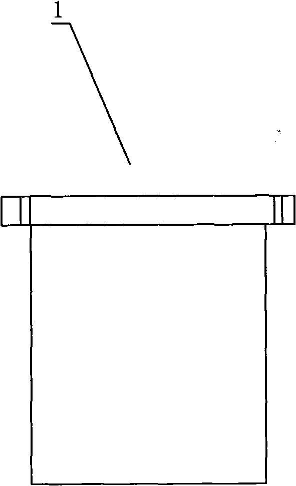
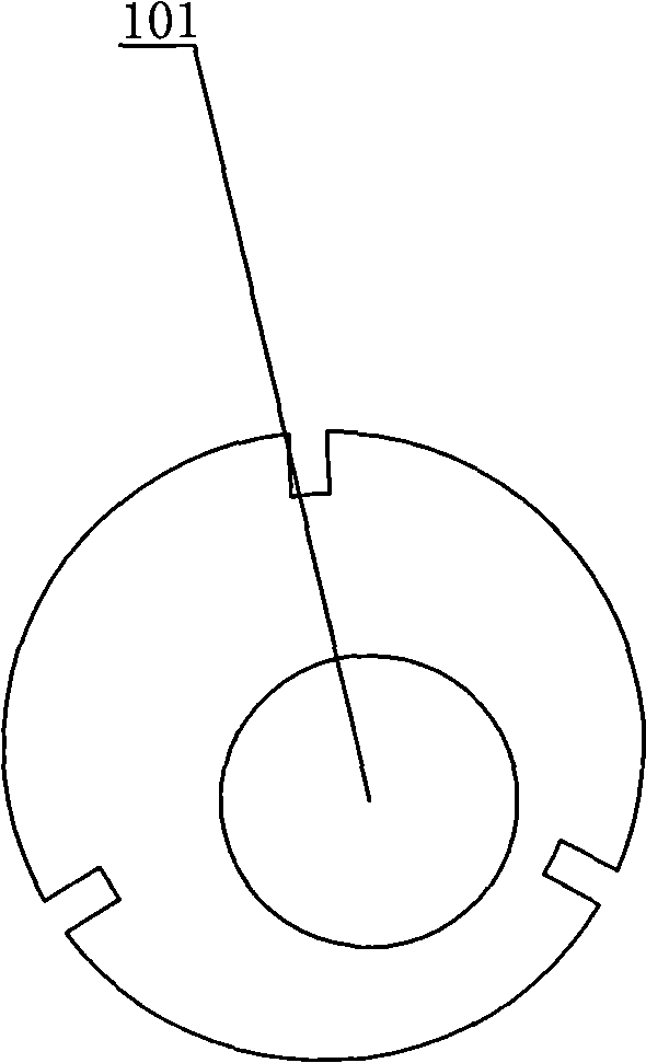
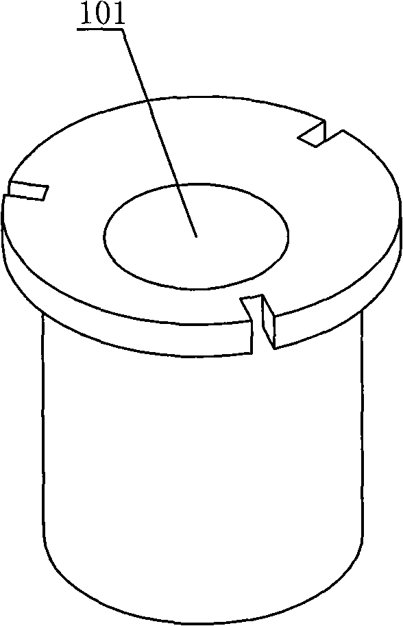
[0037] (2) Fix the glue dispensing container with an eccentric fixture and put it into the airtight cavity of the planetary centrifugal mixer; if Figure 1 to Figure 3 The shown eccentric clamp includes a glue dispensing container placement cavity 101 , and the central axis of the glue dispensing container placement cavity 101 deviates from the rotation center of the eccentric clamp 1 .

[0038](3) Start the planetary centrifugal mixer to make the glue dispensing container...


PUM


Abstract

The invention discloses a dispensing process of a white light-emitting diode (LED), in particular to a method for increasing the color centrality and reliability of the white LED and reasonably utilizing resources and energy to the maximum limit. The method comprises the following steps: mixing and stirring fluorescent powder and water, storing the mixture of fluorescent powder and water under constant temperature, stirring the mixture, pouring the mixture in a syringe of which temperature is adjustable, dispensing with a mechanical screw dispenser, placing the product in a special thermostatic feed box to send to a thermostatic oven for roasting, shortening roasting time and storing the finished product in a thermostatic rack. By using the process of the invention, the consistency of the emitting color, chromaticity coordinate and color temperature of the white LED is increased, the yield rate and reliability of the product are improved, the production process cycle of the white LED is shortened, energy is saved, resources are reasonably utilized and the production cost is reduced.

Description

technical field [0001] The invention designs a glue dispensing process method for white light LEDs. Background technique [0002] At present, LEDs are more and more widely used in various fields due to many advantages such as energy saving, environmental protection, and long life. White LEDs are gradually replacing traditional fluorescent tubes with characteristics such as high brightness, high light efficiency, and low attenuation. At the same time, in the field of backlight, white LED is also replacing the hegemony of CCFL. But no matter which field, there are high requirements for the color consistency of batches of white LEDs. The market hopes that packaging factories can achieve a certain point or a color difference and a slightly changing color temperature segment they need, but When making white light, the LED adopts the method of blue chip + carrier glue + phosphor. The parameters of the blue chip and the amount of phosphor in the white LED determine the coordinates...

Claims


Application Information

Patent Timeline
Patent Type & Authority Applications(China)
IPC IPC(8): H01L33/48
Inventor 胡康乐李德伟钟金文殷小平李国平
Owner HONGLI ZHIHUI GRP CO LTD
Learn More