Permanent magnet liquid cooling retarder for vehicle

A technology of retarder and permanent magnet, which is applied in the direction of cooling/ventilation device, magnetic circuit static parts, magnetic circuit shape/style/structure, etc. Problems such as braking torque and poor heat dissipation effect of air cooling, etc., achieve the effect of simple action, good heat dissipation effect and high reliability

Inactive Publication Date: 2012-05-23
BEIJING UNIV OF TECH +1
View PDF0 Cites 0 Cited by
  • Summary
  • Abstract
  • Description
  • Claims
  • Application Information

AI Technical Summary

Problems solved by technology

The permanent magnet retarder only has two working states of braking or non-braking, so the driver cannot provide the required braking torque according to the road conditions and vehicle speed, that is, the hierarchical control of the permanent magnet retarder cannot be realized
Moreover, the stator generates a lot of heat during braking. At present, air cooling is generally used, but the effect of air cooling is poor. When braking for a long time, the temperature of the rotor drum rises, and the braking effect decreases significantly.

Method used


Image

  • Permanent magnet liquid cooling retarder for vehicle
  • Permanent magnet liquid cooling retarder for vehicle
  • Permanent magnet liquid cooling retarder for vehicle

Examples


Embodiment 1

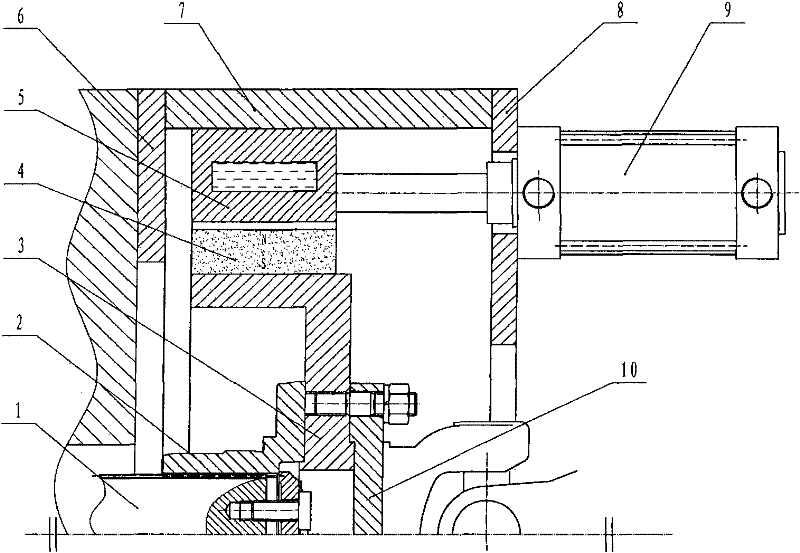
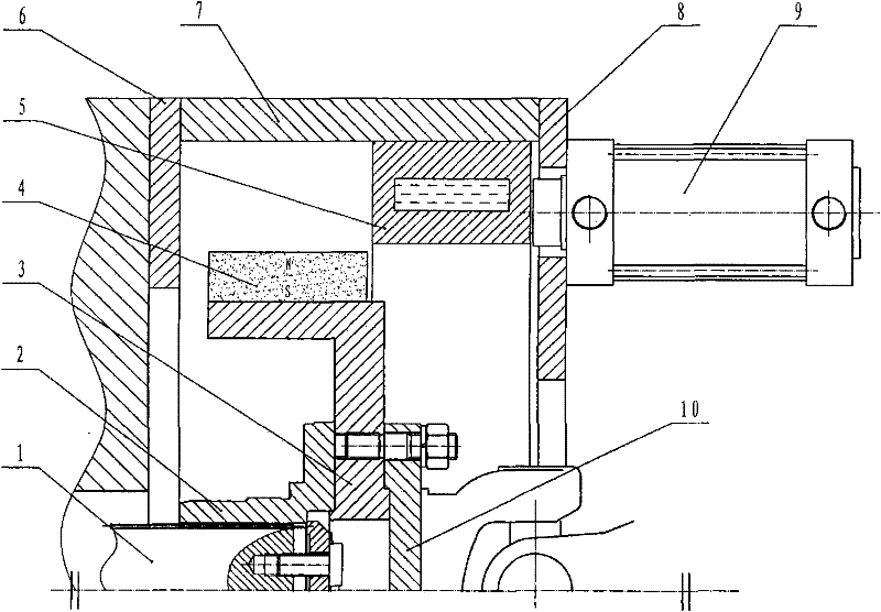
[0027] Embodiment 1 of the present invention is used for retarder to install the structure of gearbox rear body, as figure 1 with figure 2 . The left end cover 6 of the retarder is used for connecting and positioning the retarder and the gearbox, the outer shell 7 is fixed with the left end cover 6 of the retarder, and the right end cover 8 of the retarder is fixed with the outer shell 7. The stator 5 is provided with a water channel for cooling, and 1-2 cylinders 9 are fixed on the right end cover 8 of the retarder, and the pistons of the cylinders 9 are fixed with the stator 5 . 12-20 tile-shaped permanent magnets 4 are evenly distributed on the magnet holder 3 along the circumference, and the outer diameter of the permanent magnets 4 and the inner diameter of the stator drum 5 maintain a gap of 0.5-2.0 mm. The transmission output shaft 1 transmits power to the magnet holder 3 through the output shaft flange 2, and then transmits power to the automobile transmission shaft...

Embodiment 2

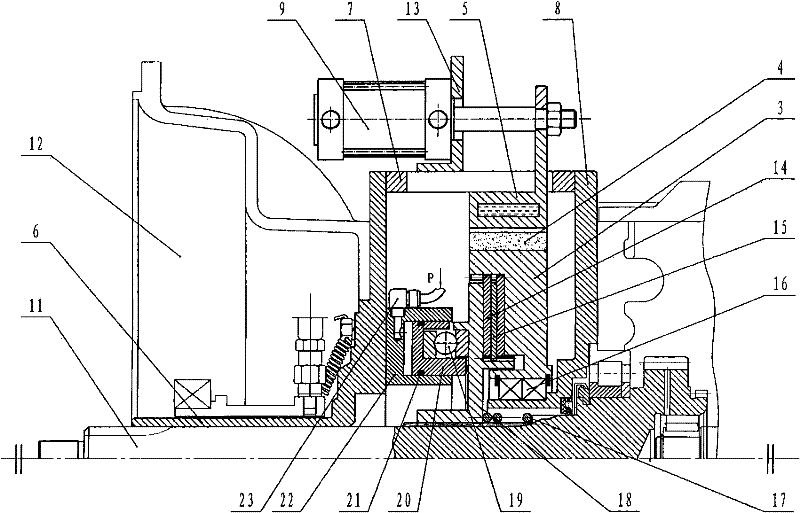
[0037] Embodiment 2 of the present invention is used for the structure that the speed retarder is installed between the gearbox and the clutch, such as image 3 . The left end cover 6 of the retarder is fixed to the clutch housing 12, the cylinder bracket 13 is fixed on the circumference of the casing 7, 1-2 cylinders 9 are fixed on the cylinder bracket 13, the casing 7 is fixed to the right end cover 8 of the retarder, and the right end of the retarder The cover 8 is fixed on the gearbox front body. There is a square groove on the circumference of the casing 7, and the boss protruding from the stator 5 is fixed with the piston of the cylinder 9 through a nut, and the piston can push and pull the stator 5 axially. Figure 8 or Figure 9 way to connect. 12-20 tile-shaped permanent magnets 4 are evenly distributed on the magnet holder 3 along the circumference, and the outer diameter of the permanent magnets 4 and the inner diameter of the stator drum 5 maintain a gap of 0.5-...

Embodiment 3

[0042] Embodiment 3 of the present invention is used to install the structure in the middle of the transmission shaft for the retarder, and is particularly suitable for being installed on automobiles with longer transmission shafts, such as Figure 5 . Divide the transmission shaft of ordinary automobiles into two sections, and install the retarder structure in the middle. The independent shaft flange 25 is connected with the drive shaft universal joint 24 at the transmission output end, and the two ends of the independent shaft 26 are respectively connected with an independent shaft flange 25 . Through the positioning bearing 16, the left end cover 6 of the retarder and the right end cover 8 of the retarder are coaxial with the independent shaft 25, and are fixed into a whole with the shell 7, and the shell 7 is fixed on the vehicle frame. The magnet holder 3 is fastened to the independent shaft 26 and rotates together with the independent shaft 26 . 12-20 tile-shaped perma...


PUM


Abstract

The invention relates to a permanent magnet liquid cooling retarder for a vehicle, belonging to an auxiliary brake system for a vehicle. The retarder comprises a shell as well as stators (5) and rotors arranged in the shell. The rotors are evenly distributed on a magnet holder (3) by a plurality of tile-shaped permanent magnets (4) along the circumference; the stators (5) are sleeved on the peripheries of the rotors; and a gap is left between the inside diameter of each stator (5) and the outside diameter of each permanent magnet (4). The automobile permanent magnet liquid cooling retarder for a vehicle is characterized in that the stators (5) can slide axially relative to the rotors and are drawn by one or two external-force devices so that the stators (5) and the rotors can be completely staggered from complete overlapping; each of the rotors is connected with an automobile transmission shaft; and each of the stators (5) is further internally provided with a cooling waterway connected with a water tank of an automobile circulation radiator. The invention ensures that a brake torque of the permanent magnet retarder is continuously adjusted as the stator slide axially in the shell, and the invention is safer compared with the traditional eddy current or permanent magnet retarder.

Description

technical field [0001] The invention relates to an auxiliary braking system for automobiles, in particular to a retarder which uses a permanent magnet as an eddy current braking magnetic source and is cooled by circulating water. Background technique [0002] The retarder is a safety auxiliary device for driving brakes, which applies the braking force to the transmission parts of the vehicle to reduce the driving speed of the vehicle. At present, the retarders commonly used at home and abroad mainly include hydraulic retarders and electric eddy current retarders. Although their working principles are different, as an auxiliary braking device, their effects are obvious. The permanent magnet type retarder uses its own permanent magnet to form a magnetic field to play a retarding role, so there is almost no power consumption. [0003] The biggest features of the permanent magnet retarder are: 1. It can realize a substantial reduction in weight and miniaturization. 2. Almost n...

Claims


Application Information

Patent Timeline
Patent Type & Authority Patents(China)
IPC IPC(8): H02K49/04H02K1/20H02K9/19
Inventor 李德胜马元京叶乐志周宜莉马岳北焦兵锋
Owner BEIJING UNIV OF TECH
Why Eureka
Try Eureka