
Vaporizer, material gas supply system including vaporizer and film forming apparatus using such system

A raw material gas and vaporizer technology, applied in electrical components, gaseous chemical plating, metal material coating process, etc., can solve the problems of no heat supply, low thermal conductivity, low thermal conductivity, etc., achieve simple structure and improve thermal efficiency Effect

Inactive Publication Date: 2010-07-21
TOKYO ELECTRON LTD
View PDF3 Cites 4 Cited by
  • Summary
  • Abstract
  • Description
  • Claims
  • Application Information

AI Technical Summary

Problems solved by technology

[0007] However, as mentioned above, since the above-mentioned evaporator is almost entirely made of stainless steel, the thermal conductivity is relatively low.
Therefore, the heat from the heater cannot be efficiently supplied to the heating surface side for vaporization of the evaporator.
In this way, there is a possibility that the thermal responsiveness is low and the heat supply is insufficient. Therefore, there is a problem that the generation amount of the raw material gas cannot be sufficiently increased even if the liquid raw material is atomized.
However, when the set temperature of the heater is increased, there is a possibility that the raw material itself may be thermally decomposed due to localized parts that become excessively high temperature.
In addition, in order to make up for the low thermal conductivity, the heater part is embedded in the vaporizer, but this structure has the disadvantage that the overall structure is complicated, resulting in high cost.

Method used


Image

  • Vaporizer, material gas supply system including vaporizer and film forming apparatus using such system
  • Vaporizer, material gas supply system including vaporizer and film forming apparatus using such system
  • Vaporizer, material gas supply system including vaporizer and film forming apparatus using such system

Examples


Embodiment Construction

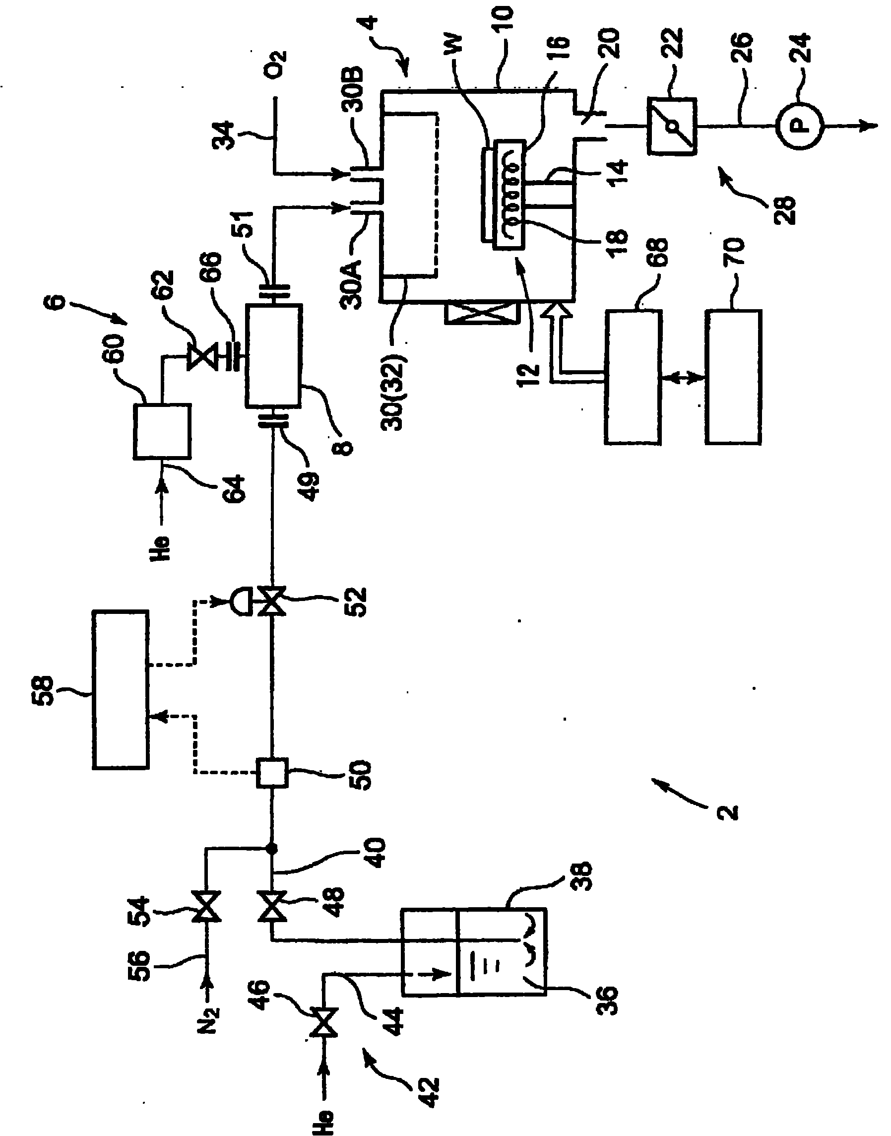
[0031] A preferred embodiment of the present invention will be described below with reference to the drawings. And in the following embodiments, for the use of tantalum pentaethoxide [Ta(OC 2 h 5 ) 5 ] (hereinafter also referred to as [PET]) as a liquid raw material, and using O 2 The gas is used as an oxidizing gas to describe an example in which a tantalum oxide film is formed on an object to be processed.

[0032] like figure 1 As shown, the film forming apparatus 2 of the present embodiment includes a film forming apparatus main body 4 as a gas use type, and a source gas supply system 6 for supplying a source gas to the film forming apparatus main body 4 . The film-forming apparatus main body 4 performs film-forming processing on a semiconductor wafer W as an object to be processed. A vaporizer 8 is provided in the raw material gas supply system 6 .

[0033] First, the film formation apparatus main body 4 will be described. like figure 1 As shown, the film forming ap...


PUM

PropertyMeasurementUnit
thermal stressaaaaaaaaaa

Abstract

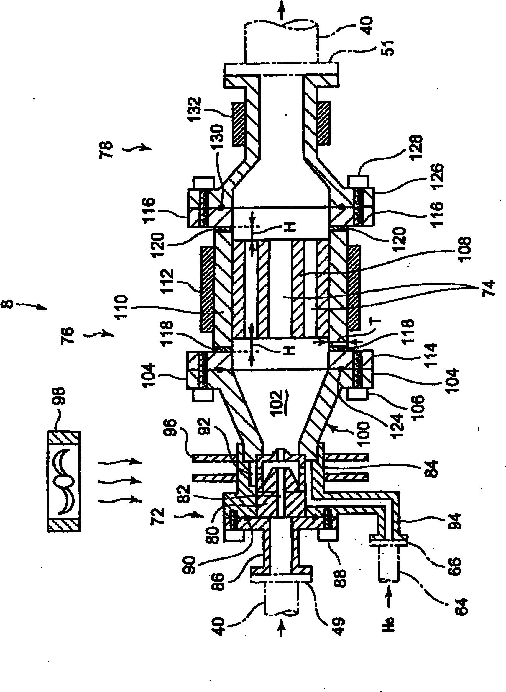
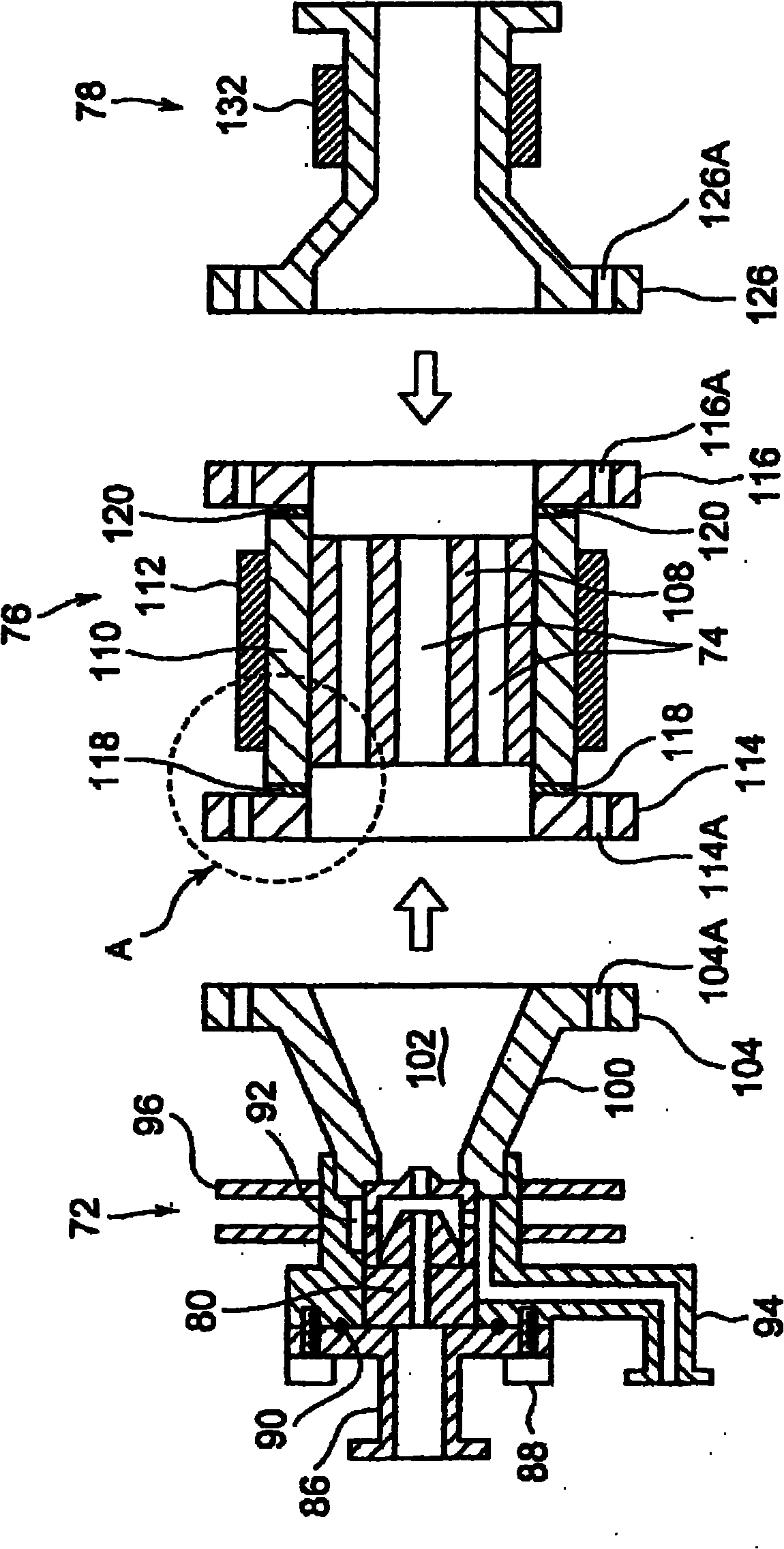
Provided is a vaporizer which has a simple structure with improved thermal efficiency. A vaporizer (8) is provided with a nozzle unit (72) for jetting a liquid material in a mist state; a vaporizing unit (76) having a plurality of vaporizing paths (74) which vaporize the material mist and form a material gas; and an ejection head (78) for sending the material gas to the subsequent stages. The vaporizing unit is provided with a vaporizing unit main body (108) wherein the vaporizing paths are formed; a main body container (110) for storing the vaporizing unit main body (108); a heater (112) for heating the material mist passing through the vaporizing paths; and connecting members (114, 116) arranged on the both end sections of the main body container. The vaporizing unit main body and the main body container are composed of a material having thermal conductivity higher than that of the material constituting the connecting members. The end sections of the main body container and the connecting members are bonded by explosion bonding.

Description

technical field [0001] The present invention relates to a film forming apparatus for forming a thin film on the surface of a target object such as a semiconductor wafer, a supply system for supplying a source gas thereto, a vaporizer used in the supply system, and a vaporization unit incorporated in the vaporizer. Background technique [0002] Generally, when manufacturing a semiconductor device, film formation processing and pattern etching processing on a semiconductor wafer are repeatedly performed. Among these processes, especially with regard to the film formation technology, the specifications are becoming stricter year by year along with the increase in density and integration of semiconductor devices. For example, thinner films are required for capacitor insulating films in devices, metal oxide films used for gate insulating films, barrier films, dielectric films, and various insulating films. [0003] In the above-mentioned thin film, especially when forming a thin...

Claims


Application Information

Patent Timeline
Patent Type & Authority Applications(China)
IPC IPC(8): H01L21/31B23K20/08C23C16/448
CPCC23C16/4486B23K20/08
Inventor 田中澄小松智仁二村宗久
Owner TOKYO ELECTRON LTD
Learn More