

Motor driven CVT (continuously variable transmission) electro-hydraulic control system
An electro-hydraulic control system, motor-driven technology, applied in transmission control, mechanical equipment, transmission, etc., can solve the mutual interference between speed ratio control and clamping force control, affect the working performance of the continuously variable transmission, and the effective range of the pressure valve. Reduce and other problems, to solve the problem of throttling power loss, the effect of energy saving is remarkable, and the effect of reducing power loss
- Summary
- Abstract
- Description
- Claims
- Application Information
AI Technical Summary
Problems solved by technology
Method used
Image

Examples
Embodiment Construction
[0021] The present invention will be described in further detail below in conjunction with the accompanying drawings and specific embodiments.
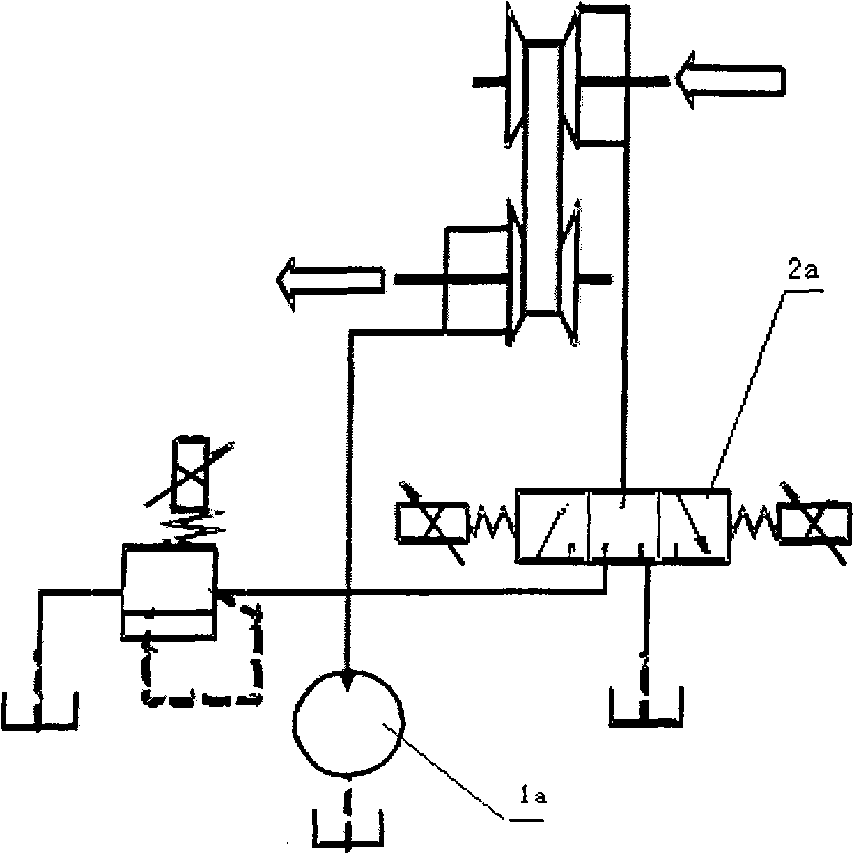
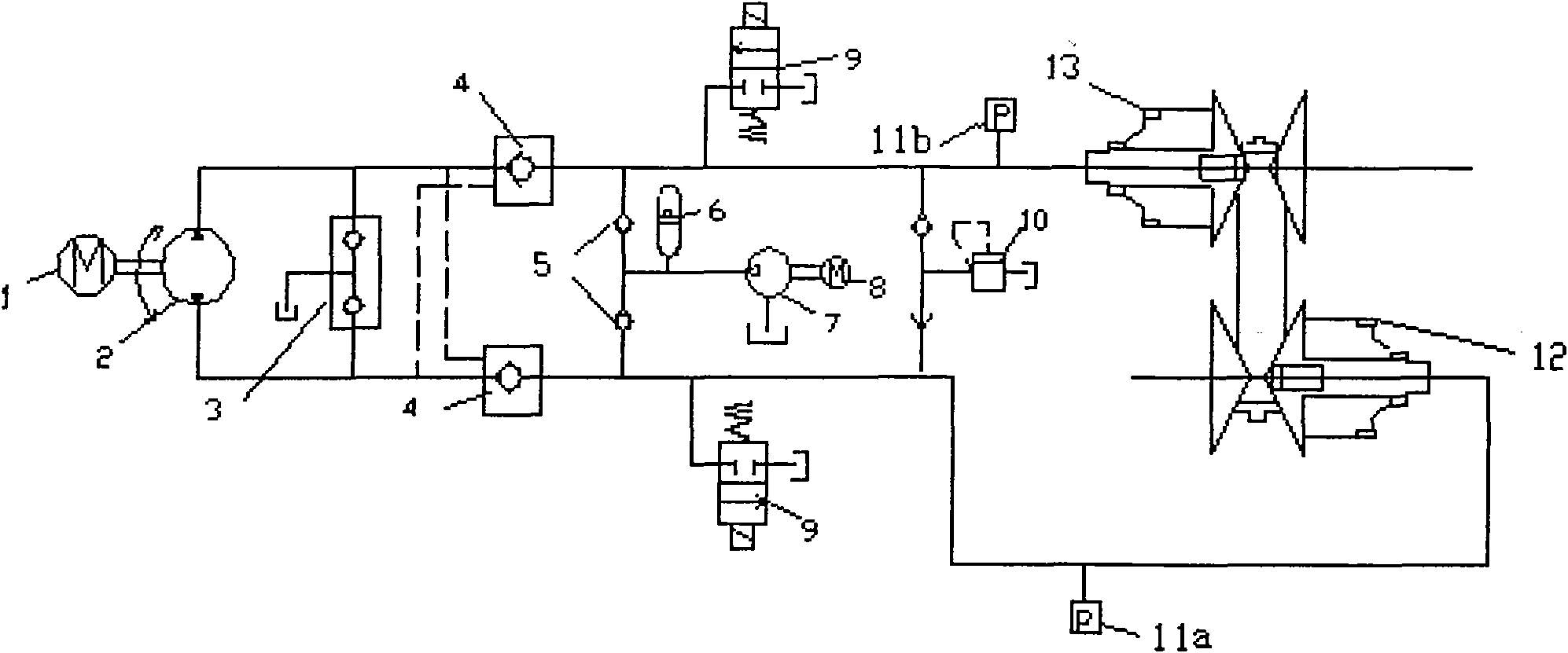
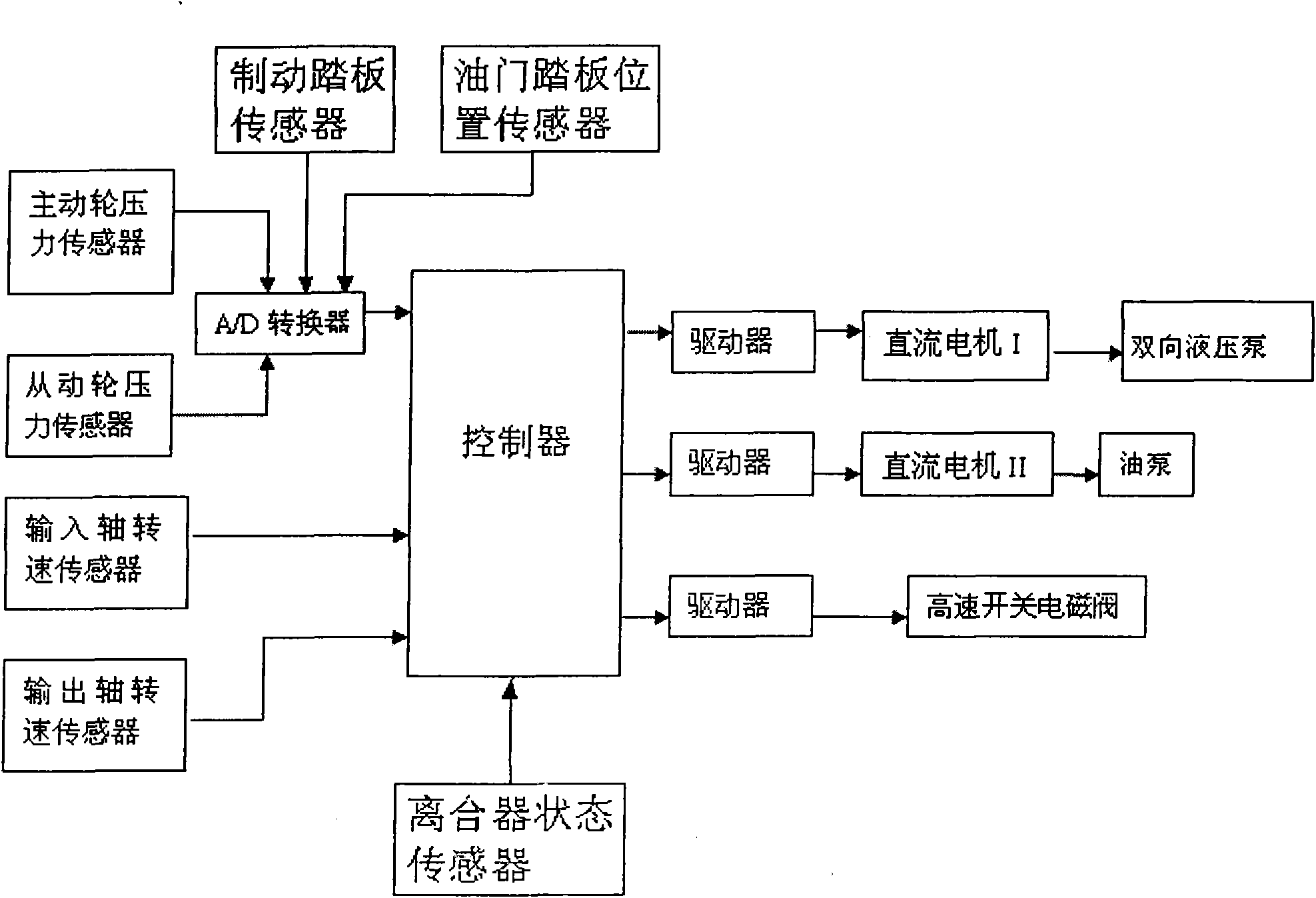
[0022] figure 2 It is a structural schematic diagram of the motor-driven CVT electro-hydraulic control system of the present invention, image 3 It is a block schematic diagram of the motor and solenoid valve control circuit, as shown in the figure: the motor-driven CVT electro-hydraulic control system includes the driving wheel hydraulic cylinder 12, the driven wheel hydraulic cylinder 13, the motor and solenoid valve control circuit, and the parallel connection in the driving wheel hydraulic cylinder. The speed ratio control loop and the clamping force control loop on the cylinder 12 and the driven wheel hydraulic cylinder 13. In this embodiment, CVT (Continuously Variable Trans-mission) refers to a continuously variable transmission.
[0023] The speed ratio control loop includes a DC motor I1, a two-way hydraulic pump 2, a shut...
PUM
 Abstract
Description
Claims
Application Information