Vehicle permanent magnetic synchronous motor and stator iron core capable of weakening magnetic resistance moment

A technology for permanent magnet synchronous motors and stator cores, applied to synchronous motors with stationary armatures and rotating magnets, magnetic circuit stationary components, magnetic circuit shape/style/structure, etc. Accuracy, high-speed and stable operation, system over-current protection device does not have enough time to act, unable to prevent the rise of the armature reaction flux, etc., to improve the rapid response capability, facilitate high-speed operation, and prevent the rise of the armature reaction flux

Inactive Publication Date: 2010-07-28
李嘉琛 +1
View PDF0 Cites 12 Cited by
  • Summary
  • Abstract
  • Description
  • Claims
  • Application Information

AI Technical Summary

Problems solved by technology

[0003]At present, the permanent magnet brushless DC motor (PMBLM) is being developed at home and abroad, and its armature excitation is a "non-circular jumping" rotating magnetic field, which has a large Torque fluctuations affect the motor's high efficiency, high precision, high speed and smooth operation
However, during the use of the existing permanent magnet brushless DC motor, since the armature reaction flux cannot be prevented from rising

Method used


Image

  • Vehicle permanent magnetic synchronous motor and stator iron core capable of weakening magnetic resistance moment
  • Vehicle permanent magnetic synchronous motor and stator iron core capable of weakening magnetic resistance moment
  • Vehicle permanent magnetic synchronous motor and stator iron core capable of weakening magnetic resistance moment

Examples


Embodiment Construction

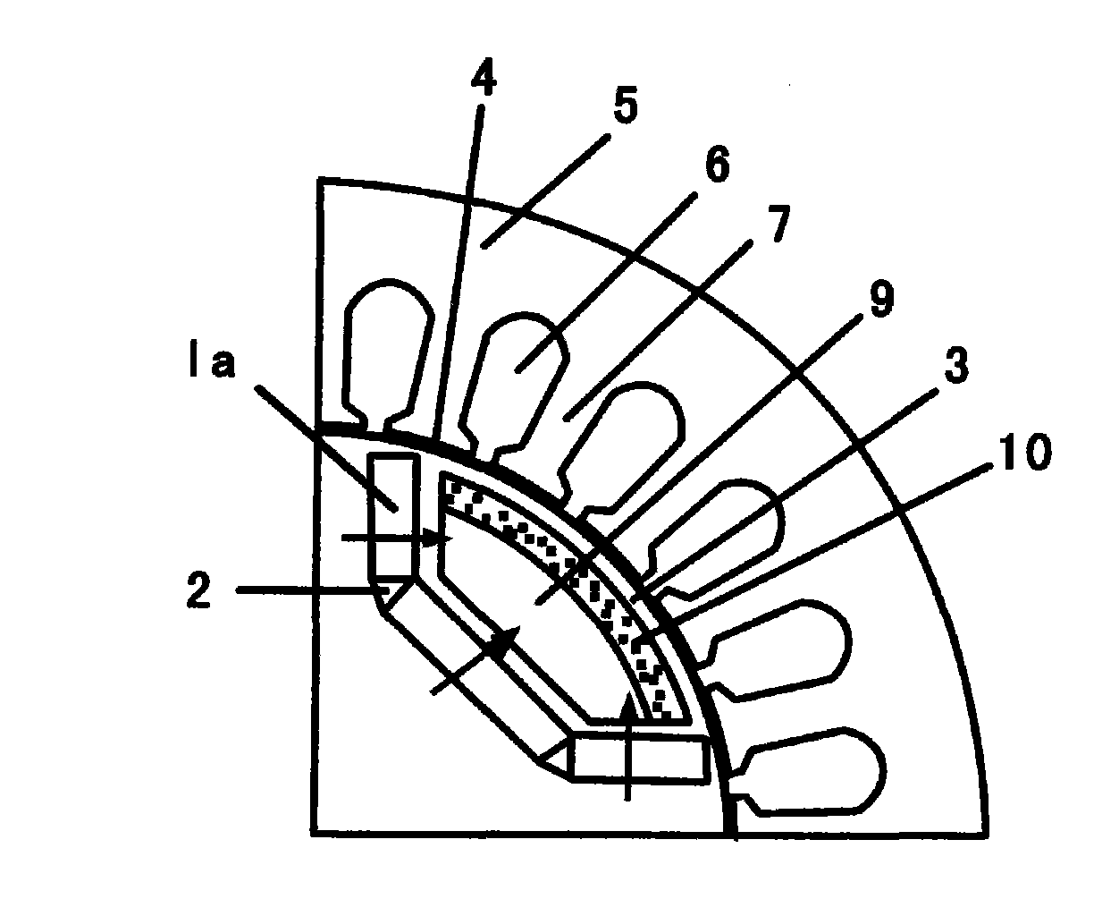
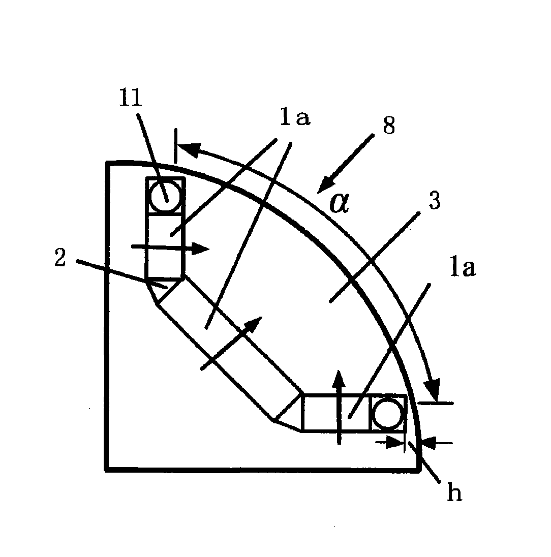
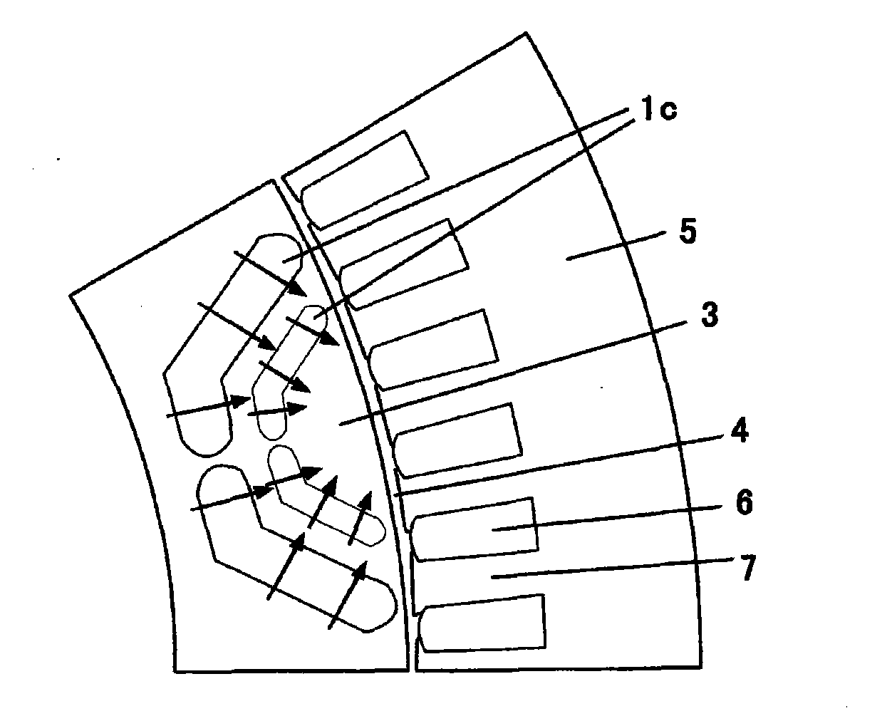
[0034] Such as figure 1 As shown, the present invention provides a permanent magnet synchronous motor for vehicles. A stator and a rotor are installed inside the casing. The stator is composed of a stator core fixed on the inner wall of the casing and a stator winding. The stator core includes a stator yoke 5 , stator slots 6 and stator teeth 7, the rotor is composed of a rotating shaft and a rotor core, and radially magnetized magnetic steel is evenly inlaid in the circumferential direction inside the rotor core, and the magnetic steel and the pole shoes 3 on the outside form permanent magnetic poles, forming The last permanent magnet poles play the role of magnetic concentration, improvement of air gap magnetic field waveform, reduction of torque ripple, and suppression of static and dynamic armature reactions. The magnetic force lines emitted from the surface of the magnetic steel extend to the pole piece and converge at the center of the magnetic pole to form a magnetic po...


PUM


Abstract

The invention relates to a vehicle permanent magnetic synchronous motor, wherein radial magnetized magnet steels are uniformly inlaid in the circumferential direction of the inside of a rotor iron core, the magnet steels and a pole shoe form a permanent magnetic pole, a fan-shaped cavity is arranged at the inside of the pole shoe, a cambered conductive starting strip and a resin filling are respectively arranged at the outer margin and the inside of the cavity, and the structure can prevent the permanent demagnetization of the magnet steels due to static and dynamic armature reactions, improve starting torque and peak torque, reduce rotor inertia and centrifugal force and improve fast response capability; a stator iron core applied to the synchronous motor is formed by sequentially overlying three layers of iron cores with different stator punching sheet tooth surfaces, wherein the first layer of iron core comprises a stator punching sheet of which the tooth surface is rightwards moved at a theta angle, the second layer of iron core comprises the stator punching sheet of which the tooth surface is leftwards and rightwards moved at a theta/2 angle, the third layer of iron core comprises the stator punching sheet of which the tooth surface is leftwards moved at the theta angle, the tooth surfaces of the three layers of iron cores are overlaid to form a skewed tooth, and the structure can weaken the magnetic resistance moment, inhabit tooth slot moment fluctuation and avoid the defect of an iron core skewed slot.

Description

technical field [0001] The invention relates to the technical field of motors, in particular to a permanent magnet synchronous motor for vehicles and a stator core capable of weakening magnetic resistance torque. Background technique [0002] The current sustainable development of the automobile industry is facing two major problems: environmental pollution and lack of oil resources. Exhaust pollution, noise, fire hazards of fuel storage and other issues of automobiles have attracted more and more attention. Environmental protection and energy saving are an important development direction of automobile technology in the 21st century. Electric vehicles have become a new generation of clean energy vehicles. Among them, the drive motor and transmission system are the heart of the electric vehicle, and the motor is the core of the drive system. The comprehensive performance of the motor directly affects the performance of the electric vehicle. At present, the drive motor for el...

Claims


Application Information

Patent Timeline
IPC IPC(8): H02K21/14H02K1/16
Inventor 李嘉琛林德芳
Owner 李嘉琛
Why Eureka
Try Eureka