Sensing method of optical-fiber Bragg grating laser device
A fiber Bragg and sensing method technology, applied in instruments, scientific instruments, and optical devices, etc., can solve the problems of low measurement accuracy, easy interference of fiber grating sensing signals, and unstable sensing systems.
- Summary
- Abstract
- Description
- Claims
- Application Information
AI Technical Summary
Problems solved by technology
Method used
Image
Examples
specific Embodiment approach 1
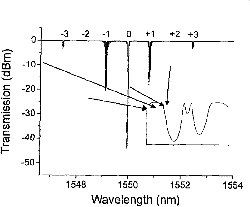
[0064] Specific implementation mode one: as figure 2 As shown, two three-section fiber Bragg gratings 31 with an equivalent π phase shift interval and a length of 6.8 cm are written into the erbium-doped fiber 21, and the effective refractive index of the fiber core is 1.447. Through theoretical simulation, we can obtain the Fiber Bragg Grating theoretical transmission spectrum, such as image 3 shown. Here we can see that zero and even orders have no transmission peaks, so no lasing can be formed. There are two peaks in each odd-numbered transmission spectrum, and the depth of ±1 order is the deepest, that is, the energy is the highest, and they may form lasing. Due to the short-wavelength loss of the fiber, the -1 class is more likely to generate lasing than the +1 class. Through such analysis, we can know that our three-segment fiber grating structure can only generate stable two-wavelength laser light at the +1 order. The two laser wavelengths obtained are 1556.454nm ...
specific Embodiment approach 2
[0065] Specific implementation mode two: as Figure 5 As shown, this specific embodiment is an example of a demodulation device for a dual-wavelength fiber Bragg grating laser sensing method. The device consists of 980 or 1480nm pump light source 1, 980nm / 1550nm wavelength division multiplexer 2, sensor probe 3 is a dual-wavelength fiber Bragg grating laser, the fixed end of the micro-motion platform 4-1, and the adjustable end of the micro-motion platform 4-2 , an erbium-doped fiber amplifier 7, a high-frequency photodetector 5, and a spectrum analyzer 6. The light of the 980nm pump laser 1 is incident on the dual-wavelength fiber Bragg grating laser through the wavelength division multiplexer 2 to generate dual-wavelength laser light. The interference beat frequency signal of the two lasers is amplified by the fiber amplifier 7 , converted into an electrical signal by the high frequency photodetector 5 , and then detected by the spectrum analyzer 6 . The fiber grating lase...
specific Embodiment approach 3
[0066] Specific embodiment three: In order to avoid mode competition, the wavelength spacing of the dual-wavelength laser cannot be less than 40pm, so that the beat frequency signal of the sensor cannot be lower than 5GHz. In the second embodiment, the beat frequency of the dual-wavelength laser is 10.125GHz, which is High-speed photodetectors and spectrometers are required, and they require high prices and volumes, which are not convenient for cost-effectiveness and promotion of use. We can use the electro-optic modulator to reduce the beat frequency signal from high frequency to low frequency band, so that the sensor beat frequency signal can be detected by low frequency photodetector and spectrum analyzer. Such as Figure 7 Shown, the device of this specific embodiment consists of 980 pump light source 1, 980nm / 1550nm wavelength division multiplexer 2, sensing probe 3 is a dual-wavelength fiber Bragg grating laser, and the fixed end 4-1 of the micro-motion platform, the mic...
PUM
| Property | Measurement | Unit |
|---|---|---|
| length | aaaaa | aaaaa |
| refractive index | aaaaa | aaaaa |
Abstract
Description
Claims
Application Information
 - R&D
- Intellectual Property
- Life Sciences
- Materials
- Tech Scout
- Unparalleled Data Quality
- Higher Quality Content
- 60% Fewer Hallucinations
Browse by: Latest US Patents, China's latest patents, Technical Efficacy Thesaurus, Application Domain, Technology Topic, Popular Technical Reports.
© 2025 PatSnap. All rights reserved.Legal|Privacy policy|Modern Slavery Act Transparency Statement|Sitemap|About US| Contact US: help@patsnap.com


