Fixed gantry stand of high-depth automatic drilling machine

A gantry frame, fixed technology, applied in the field of machine tools, can solve the problems of inclination of holes, poor concentricity of holes, poor stability, etc., and achieve the effects of simple mechanism, reliable installation and convenient operation.

Inactive Publication Date: 2010-08-11
应云富
2 Cites 0 Cited by

AI-Extracted Technical Summary

Problems solved by technology

The radial drilling machine is connected by the rocker arm to the parallel power head (the power head is installed with the drill bit) and the frame. The rocker arm can rotate 360° around the column, and can also rise and fall along the column. The headstock can move along the horizontal guide rail of the rocker arm. , align the workpiece by moving the power head, which is suitable for processing large workpieces, but because the center of force of the power head and the center of gravity of the frame are not on the same line, that is, there is an offset between the two, so when drilling deep holes When drilling, not only the rocker arm will tremble, but the power head will tilt, and the hole will be tilted, so it is not suitable for drilling deep holes; the center of force of the power head of the existing vertical drilling machine and the frame (used to fasten the power he...

Abstract

The invention discloses a fixed gantry stand of a high-depth automatic drilling machine, comprising a machine seat connected with a stand; and the stand is provided with a fastening mechanism which is fixedly connected with a power head. The fixed gantry stand is characterized by comprising a vertical plate and a transverse plate which are vertical to each other and fixedly connected; the vertical plate is fixed on the machine seat; the fastening mechanism comprises a fastening hole formed in the transverse plate; and the power head is arranged in the fastening hole in which a locking mechanism is arranged. The technical scheme has remarkable advantages and beneficial effect that: firstly, the invention is mainly applicable for keeping the aperture in the same center and unchanged during automatically drilling deep holes; secondly, the structure is especially simple, the engine seat is respectively and fixedly connected with the vertical plate and the transverse plate, the mounting is reliable and the movement and the debugging are not needed; and thirdly, the fastening hole is directly punched in the transverse plate and used for mounting the power head, the mechanism is simple and the operation is simple.

Application Domain

Technology Topic

Deep holeDrilling machines +1

Image

  • Fixed gantry stand of high-depth automatic drilling machine
  • Fixed gantry stand of high-depth automatic drilling machine
  • Fixed gantry stand of high-depth automatic drilling machine

Examples

  • Experimental program(1)

Example Embodiment

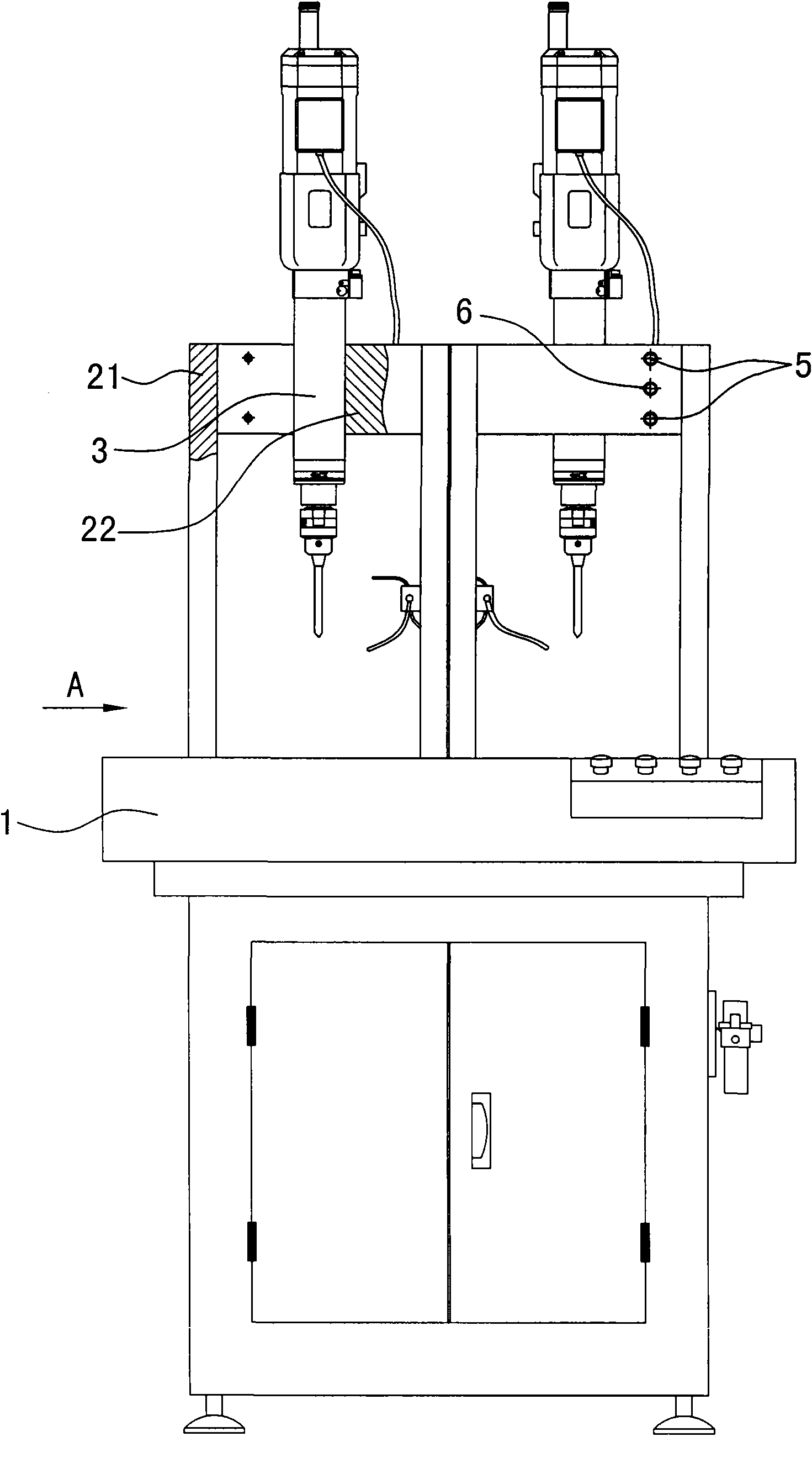
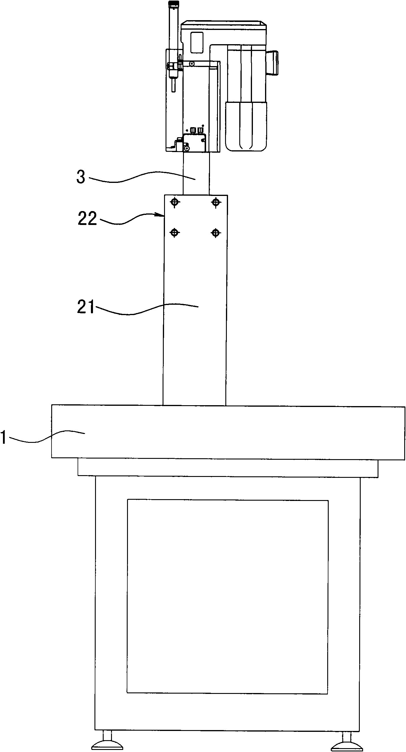
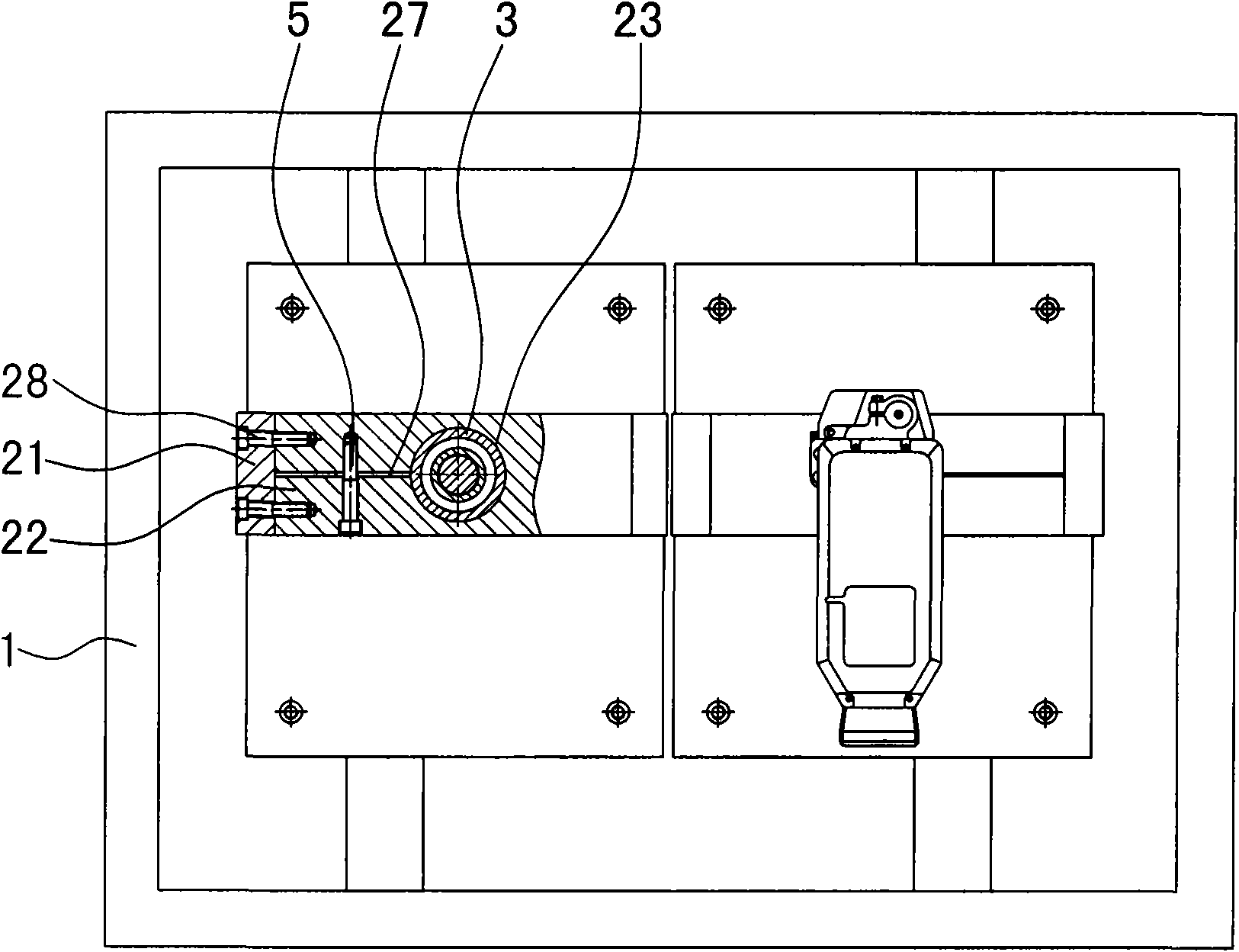
[0011] The invention discloses a fixed gantry frame of a high-depth automatic drilling rig, such as figure 1 , figure 2 As shown, the frame includes a machine base 1, which is connected to a frame, the frame has a fastening mechanism, and the fastening mechanism is fixedly connected to the power head. It is characterized in that the frame includes a vertical plate 21 and a horizontal plate 22 that are perpendicular to each other. Fixed connection, the vertical plate is fixed on the base 1, the fastening mechanism includes a fastening hole 23 made in the horizontal plate 22, the power head 3 is installed in the fastening hole 23, and the fastening hole 23 has a locking mechanism The frame is mainly composed of a vertical plate 21 including columns, poles, etc. and a horizontal plate 22 (beam). The vertical plate 21 and the horizontal plate 22 are perpendicular to each other in a "gantry type" and fixedly connected to the machine base 1. , And a fastening hole 23 is directly made in the horizontal plate 22, and the fastening hole 23 is used as a fastening mechanism to install the power head 3 in the fastening hole 23, so that the center and the center of gravity of the power head 3 include weight and downward The drilling force is consistent with the center of the horizontal plate 22 and the vertical plate 21. When the drilling rig is drilling a deep hole of 200mm or more, the drill will not be deflected due to the influence of the recoil force on the frame, and neither Affected by the moving mechanism of the drill press. Therefore, the outstanding advantages and significant effects of this technical solution are as follows: First, it is mainly suitable for automatic drilling of deep holes, including deep holes of 200mm, with the aperture remaining at the same center; second, the structure is particularly simple, the machine base and vertical plate, horizontal The plates are all fixed connections, which are reliable in installation, will not move, and do not need to be debugged; third, the power head is installed directly in the fastening hole in the horizontal plate, the mechanism is simple and the operation is convenient. Such as image 3 As shown, the locking mechanism includes an opening groove 27 formed in the middle of the horizontal plate 22, one end of the opening groove 27 communicates with the fastening hole 23, the other end of the opening groove 27 is closed by the vertical plate 21, and the opening groove 27 The two side walls are connected by a locking screw 5, and the power head can be installed and unloaded and adjusted through an open slot, which is convenient for operation and reliable for installation. When adjusting the height of the power head, first disassemble the connecting piece between the vertical plate 21 and the horizontal plate 22, then loosen the locking screw 5, open the opening slot 27, make the fastening hole 23 larger, and then move the power up and down The head 3 is in the proper position, and finally the locking screw 5 is screwed on, so that the opening groove 27 is reset, and the fastening hole 23 is reduced to automatically hold the housing of the power head 3. The said locking screw 5 is one or two or three, such as figure 2 As shown, there are 2 locking screws. Such as Figure 4 As shown, the top screw 6 is installed on one side of the horizontal plate 22. The tail of the top screw 6 passes through the opening groove 27 and contacts the wall surface of the opening groove 27. As long as the top screw 6 is turned, it can be quickly , The opening slot 27 is effectively topped. The said top screw 6 is one or two or three. The vertical plate 21 and the horizontal plate 22 are connected by a fixing screw 28, which is convenient to install and reliable in connection. Other fasteners or connection mechanisms can also be used.

PUM

no PUM

Description & Claims & Application Information

We can also present the details of the Description, Claims and Application information to help users get a comprehensive understanding of the technical details of the patent, such as background art, summary of invention, brief description of drawings, description of embodiments, and other original content. On the other hand, users can also determine the specific scope of protection of the technology through the list of claims; as well as understand the changes in the life cycle of the technology with the presentation of the patent timeline. Login to view more.

Similar technology patents

Classification and recommendation of technical efficacy words

  • Simple structure
  • Reliable installation

Microlithographic projection exposure apparatus

InactiveUS20050068499A1Simple structureReliable and low-maintenance operationProjectorsPhotomechanical exposure apparatusCamera lensPhysics
Owner:CARL ZEISS SMT GMBH

Insertion strip for cars and mounting structure thereof

InactiveCN101314346AReliable installationSimplify manufacturing stepsVehicle componentsEngineeringHelix
Owner:KATAYAMA KOGYO CO LTD
Why Eureka
Try Eureka