
Hydrogen production method and device based on aluminum or magnesium underwater stir friction welding process

A friction stir and welding process technology, applied in hydrogen production and other directions, can solve the problems of polluting the environment, complex processes, and high hydrogen production costs, and achieve the effects of simple hydrogen production methods, high hydrogen production efficiency, and low hydrogen production costs.

Inactive Publication Date: 2010-08-11
HARBIN INST OF TECH
View PDF1 Cites 9 Cited by
  • Summary
  • Abstract
  • Description
  • Claims
  • Application Information

AI Technical Summary

Problems solved by technology

[0003] The purpose of the present invention is to provide a hydrogen production method and device based on the friction stir welding process in aluminum or magnesium water, in order to solve the complex process of the existing biological hydrogen production method, pollute the environment, and the existing electrolytic water hydrogen production and chemical reaction hydrogen production methods Both need to add chemical reagents or alloy elements, causing pollution to the environment while producing hydrogen, poor controllability, and high hydrogen production costs

Method used


Image

  • Hydrogen production method and device based on aluminum or magnesium underwater stir friction welding process
  • Hydrogen production method and device based on aluminum or magnesium underwater stir friction welding process

Examples


specific Embodiment approach 1

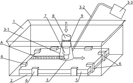
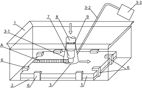
[0008] Embodiment 1: Combining figure 1 Describe this embodiment, this embodiment is realized through the following steps: Step 1, install the aluminum plate or magnesium plate 5 of the workpiece to be welded: place the aluminum plate or magnesium plate 5 of the workpiece to be welded on the upper end surface of the stainless steel backing plate 2, use a clamp Tool 6 firmly positions the aluminum plate or magnesium plate 5 of the workpiece to be welded and the stainless steel backing plate 2; Step 2, water injection: inject water into the water tank 1, and the water level exceeds the upper end surface of the aluminum plate or magnesium plate 5 of the workpiece to be welded 30mm~50mm; Step 3. Select the parameters of welding tool 7: the diameter of the shoulder of the stirring head on the welding tool 7 is 20mm~40mm, the diameter of the stirring needle is 5mm~10mm, and the length of the stirring needle is 5mm~10mm; Step four, install the welding tool 7: Install the clamping bod...

specific Embodiment approach 2

[0009] Specific implementation mode 2: Combining figure 1 Illustrating this embodiment, in step 5 of this embodiment, the material of the collecting cover 3-1 is plexiglass. Plexiglass is both transparent and visible, and not easily broken. Other steps are the same as in the first embodiment.

specific Embodiment approach 3

[0010] Specific implementation three: combination figure 1 This embodiment will be described. This embodiment is composed of a water tank 1, a stainless steel backing plate 2 and a hydrogen gas collection assembly 3. The hydrogen gas collection assembly 3 is composed of a collection cover 3-1, an air duct 3-2 and a reservoir 3-3. The air duct 3 One end of -2 is communicated with the collection cover 3-1, the other end of the gas duct 3-2 is communicated with the reservoir 3-3, the stainless steel backing plate 2 is placed on the bottom end surface of the water tank 1, and the hydrogen collection assembly 3 is located on the stainless steel backing plate 2, and the collection cover 3-1 on the hydrogen collection assembly 3 is placed perpendicular to the stainless steel backing plate 2.

[0011] Specific embodiment four: combination figure 1 Describing the present embodiment, the collecting cover 3 - 1 of the present embodiment has a conical shape, and the large diameter end ...


PUM


Abstract

The invention provides hydrogen production method and device based on an aluminum or magnesium underwater stir friction welding process, relating to hydrogen production method and device. The invention aims to solve the problems of complex process and environmental pollution of the traditional biological hydrogen production method and necessary addition of chemical agents or alloy elements in both the traditional electrolytic water hydrogen production method and the traditional chemical reaction hydrogen production method. The method comprises the following steps of firstly, installing a welded aluminum plate or a welded magnesium plate; secondly, injecting water; thirdly, selecting parameters of a welding tool; fourthly, installing the welding tool; fifthly, installing a hydrogen collection component; sixthly, carrying out stir friction welding on the welded aluminum plate or the welded magnesium plate; and seventhly, generating hydrogen when carrying out chemical reaction on the welded part of the aluminum plate or the magnesium plate and water in the stir friction welding seam forming process, continuously generating the hydrogen, collecting the hydrogen into a collection cover, and finishing hydrogen preparation by introducing the hydrogen into a storage container through an airway. In the device, a stainless steel cushion plate is arranged at the bottom of a water groove, the hydrogen collection component is arranged above the stainless steel cushion plate, and the collection cover is vertical to the stainless steel cushion plate. The invention is used for preparing hydrogen.

Description

technical field [0001] The present invention relates to a hydrogen production method and device. Background technique [0002] Hydrogen energy is an efficient and clean energy source. Due to its strong renewable ability, low environmental pollution and large heat production, hydrogen energy has received more and more attention in recent years for its research and application. Existing hydrogen production methods include biological hydrogen production, water electrolysis hydrogen production and chemical reaction hydrogen production. Biological hydrogen production is the use of activated sludge to ferment organic matter in organic wastewater to produce hydrogen-containing fermentation gas, which is eluted by lye. After the carbon dioxide is removed from the tower, hydrogen is produced. This method is complicated in process, pollutes the environment, has a low conversion rate of hydrogen production, and has high cost; the existing hydrogen production by electrolysis water and c...

Claims


Application Information

Patent Timeline
IPC IPC(8): C01B3/08
CPCY02E60/36
Inventor 刘会杰张会杰李志刚冯秀丽黄永宪林梦
Owner HARBIN INST OF TECH
Learn More