Suspension device for probing falling body

A suspension device, wing plate technology, applied in the direction of measuring device, sampling device, test water, etc., can solve problems such as affecting the accuracy of measurement

Inactive Publication Date: 2010-08-11
北京南风科工应用技术有限公司
View PDF2 Cites 3 Cited by
  • Summary
  • Abstract
  • Description
  • Claims
  • Application Information

AI Technical Summary

Problems solved by technology

[0012] In the stage of falling, it is hoped that the falling body will move as close as possible to the free-falling body, so that the obtained data will be closer to the "vertical" section. However, the problem is that i...

Method used


Image

  • Suspension device for probing falling body
  • Suspension device for probing falling body
  • Suspension device for probing falling body

Examples


Embodiment 1

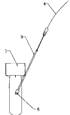
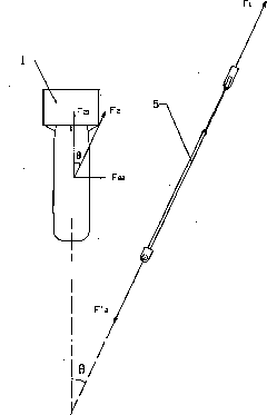
[0047] Figure 4 It is the front view of the suspension device for detecting the falling body in this embodiment, Figure 5 It is a side view of the suspension device in this embodiment in the state of detecting the falling body. In order to clearly illustrate the function of the suspension device, the detection pendant is shown by dotted lines in the figure.

[0048] As shown in the figure, the suspension device 10 for detecting a falling body includes: a bar 11 , a first wing 12 and a traction part 13 .

[0049] Wherein, the handle bar 11 is substantially U-shaped, axisymmetric to the center line B-B, and its center of gravity is also located on the center line B-B. One end of the rod 11 is open and the other end is closed. The U-shaped open end 111 is used for rotating connection with the detection falling body 1 , and the U-shaped closed end 112 is connected with a traction part 13 for connecting with the towing cable 4 .

[0050] The first wing plate 12 is located in t...

Embodiment 2

[0059] Figure 7 It is the front view of the suspension device for detecting the falling body in this embodiment, Figure 8 It is a side view of the suspension device for detecting the falling body in this embodiment.

[0060] As shown in the figure, the structure of the suspension device 20 of this embodiment is basically the same as that of Embodiment 1, the main difference is that the bar 21 is provided with at least three traction points ( Figure 7 and Figure 8 Only take three as an example, that is: the first traction point a, the second traction point b and the third traction point c), the traction part 23 passes at least three slings ( Figure 7 and Figure 8 Only three flexible cables are used as an example, that is, the first flexible cable 25a, the second flexible cable 25b and the third flexible cable 25c) are flexibly connected with the handle bar 21.

[0061] Wherein, the first traction point a and the second traction point b are respectively located at or n...


PUM


Abstract

The invention provides a suspension device for a probing falling body, which comprises a handle rod and a first wing plate, wherein the handle rod is basically U-shaped, the open end of the handle rod is rotationally connected with the probing falling body, and the first wing plate is positioned in a plane encircled by the closed end of the handle rod; and the handle rod is provided with at least three traction points. The suspension device also comprises a traction part and at least three soft cables, wherein one end of each soft cable is connected with each traction point, and the other end of the each soft cable is connected with the traction part; and the suspension device can comprise a second wing plate which is basically vertically connected with the first wing plate. When the probing falling body with the suspension device falls, the water flow produces a reverse heading resistance to the first wing plate, and the direction of the resistance is opposite to the horizontal component force direction of the pull of the handle rod, so a part of horizontal component force is weakened, even eliminated, the horizontal component force of the pull of the handle rod to the probing falling body is reduced, then the transverse displacement of the probing falling body can be reduced, the falling process of the probing falling body is closer to the free falling motion, and the accuracy of measuring a hydrographic vertical profile map is further improved.

Description

technical field [0001] The invention relates to the technical field of water body measurement, in particular to a suspension device for detecting falling bodies. Background technique [0002] At present, with the rapid progress of science and technology, the development, utilization and protection of water resources (including oceans, rivers and lakes) by human beings are also developing by leaps and bounds. To develop and utilize water resources, we must first understand the water body, and hydrographic measurement of the water body is a way to understand the water body. [0003] For example, in physical oceanography, as the temperature and salinity of water layers at different depths change, the speed of sound also changes. Obtaining the above water body parameters in a specific sea area can be used for ocean mapping such as sonar velocity measurement and ranging; and For example, measuring water body parameters such as temperature and salinity (salt content) of seawater ...

Claims


Application Information

Patent Timeline
IPC IPC(8): G01N1/10G01N33/18G01C13/00
CPCY02A90/30
Inventor 方励梁敏德卢楠
Owner 北京南风科工应用技术有限公司
Why Eureka
Try Eureka