

Energy-saving bus slot
A technology of bus duct and bus side, applied in the field of low-voltage transmission and distribution line bus duct trunk system, can solve the problems of the heat dissipation surface cannot be used to the maximum, the shell is limited in structure, and the material consumption is large, so as to save resources and achieve good heat dissipation. , the effect of reducing costs
Inactive Publication Date: 2010-08-11
马纪财
View PDF4 Cites 17 Cited by
- Summary
- Abstract
- Description
- Claims
- Application Information
AI Technical Summary
Problems solved by technology
1. The shell is limited to the structure, and the heat dissipation surface cannot be utilized to the maximum extent;
2. The process is complicated, the material consumption is large, and the production efficiency is low;
3. Material cost leads to high manufacturing cost
Method used
View moreImage
Smart ImageViewing Examples

Examples
Embodiment Construction
Login to View More PUM
 Abstract
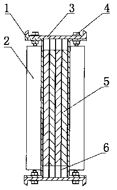
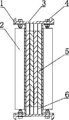
The invention relates to an energy-saving bus slot, and particularly provides a low-cost energy-saving bus slot with a high-efficiency heat radiating structure with low resistance, low reactance, low line loss and less material consumption, wherein two bus lateral plates (1) which are symmetrically arranged and a bus cover plate (3) are used as overall supports for the bus slot, a lateral plate heat radiating sheet (2) is respectively arranged at the outer sides of the two bus lateral plates (1), the cover plate (3) is positioned at the outer sides of two folding edges of the two bus lateral plates (1), the bus lateral plates (1) and the cover plate (3) are connected into a whole through fasteners (4), and a space with a rectangular cross section is formed in an area surrounded by the bus lateral plates (1) and the cover plate (3). An insulating layer (6) is respectively arranged at the inner sides of the bus lateral plates (1), and a bus conductor (5) is positioned between the insulating layers (6).
Description
Energy-saving busway technical field The invention relates to a low-voltage power transmission and distribution line busway main line system, and belongs to the technical field of electric power busway manufacturing. Background technique In order to meet the needs of high-current and low-voltage transmission lines in industrial and civil engineering construction, the power distribution design adopts the busbar trunking system. In recent years, with the continuous increase in the capacity of transmission and distribution lines, the busbar trunking system has been widely used in In the project, the structural design of the busway products ranges from air-insulated to densely insulated, from steel plate shells to aluminum alloy shells, from flat-plate shells to heat-dissipating bar shells, and the protection grades range from IP40 to IP66, which runs through the development of the entire industry In the process, the most important technical performance index of the busway is ...
Claims
Login to View More Application Information
Patent Timeline
 IPC IPC(8): H02G5/02
Inventor马纪财
Owner马纪财