Rotor position detecting device and method of permanent magnet type synchronous motor

A rotor position detection and synchronous motor technology, which is applied to starting devices, control electromechanical transmission devices, electronic commutators, etc., can solve the problems of long detection time, inability to detect current drop time, inconvenient rotor position detection devices and methods, etc.

Inactive Publication Date: 2010-08-11
RICHTEK TECH
View PDF9 Cites 17 Cited by
  • Summary
  • Abstract
  • Description
  • Claims
  • Application Information

AI Technical Summary

Problems solved by technology

However, the current method of measuring the rise time is to use a single-ended amplifier circuit to detect the current passing through the motor, so only the rise time of the current can be detected, but the fall time of the current cannot be detected, so the current drop cannot be accurately known. From the formula 3, it can be seen that the time for the current to drop to 0 may be different under different voltage vectors. Therefore, after the current rises to a critical value, it is necessary to set a longer delay time to ensure that the voltage vector is switched. When the current on the motor is 0, this will make the motor need a long detection time when starting
[0014] Therefore, there are above-mentioned inconveniences and problems in the known rotor position detection device and method.

Method used


Image

  • Rotor position detecting device and method of permanent magnet type synchronous motor
  • Rotor position detecting device and method of permanent magnet type synchronous motor
  • Rotor position detecting device and method of permanent magnet type synchronous motor

Examples


Embodiment Construction

[0108] The present invention will be further described below in conjunction with embodiment and accompanying drawing.

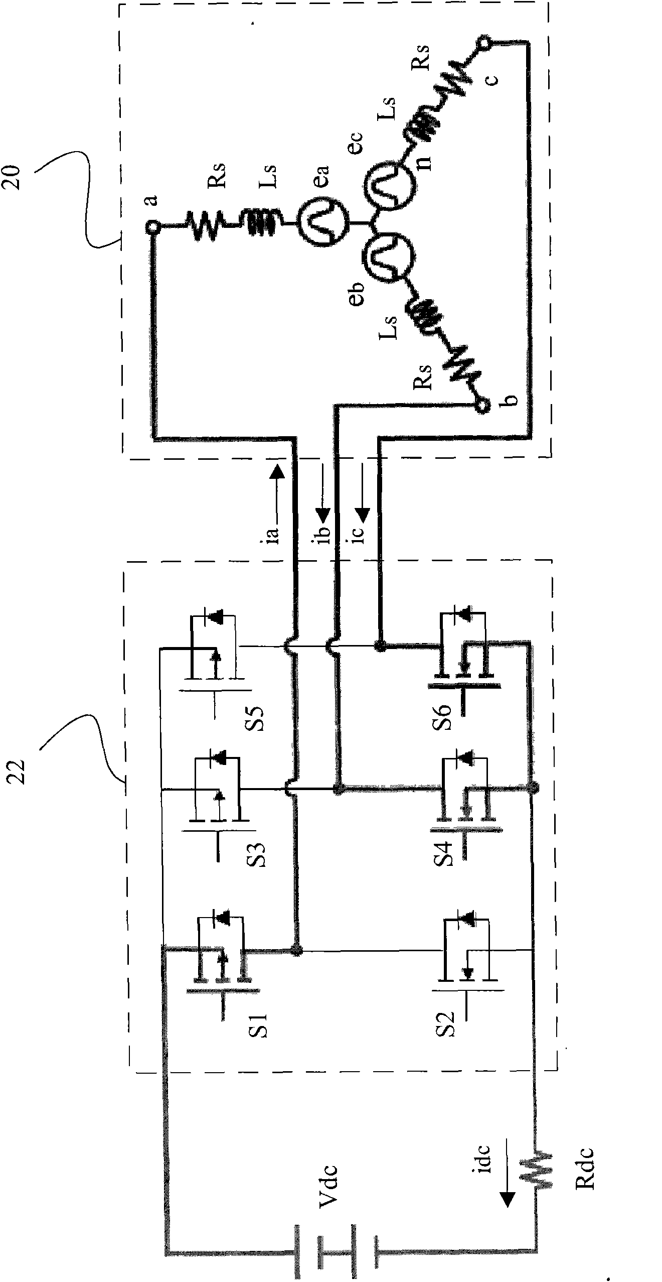
[0109] see now Figure 6 , Figure 6 The first embodiment of the present invention is shown, wherein the driver 34 switches the power switches M1-M6 in the inverter 32 according to the signal PWM_TEST from the detection circuit 46 to apply different voltage vectors to the PMSM 30, and the motor current on the PMSM 30 The related DC link current idc generates the sensing signal Vs through the shunt resistor Rdc, the sensing circuit 36 ​​generates the over-current signal OC and the zero-current signal ZC according to the sensing signal Vs, and the detection circuit 46 generates the over-current signal OC and the zero-current signal ZC according to the over-current signal OC and the zero-current signal ZC Signal PWM_TEST.

[0110] Figure 7 show Figure 6 The signal waveform in . refer to Figure 6 and Figure 7 , when the PMSM 30 is started from the stop...


PUM


Abstract

The invention relates to a rotor position detecting device of a permanent magnet type synchronous motor, which comprises a sensing assembly, a detecting circuit and a sensing circuit. The detecting device is characterized in that the sensing assembly is used for sensing the current of the permanent magnet type synchronous motor and generates a sensing signal; the detecting circuit is used for enabling a plurality of voltage vectors to act on the permanent magnet type synchronous motor in sequence; the sensing circuit is connected with the sensing assembly and generates an overcurrent signal and a zero-current signal to the detecting circuit according to the sensing signal, wherein the detecting circuit counts the total conducting time of the current flowing through the motor under each voltage vector according to the overcurrent voltage and the zero-current signal, and the rotor position of the permanent magnet type synchronous motor is judged according to the total conducting time.

Description

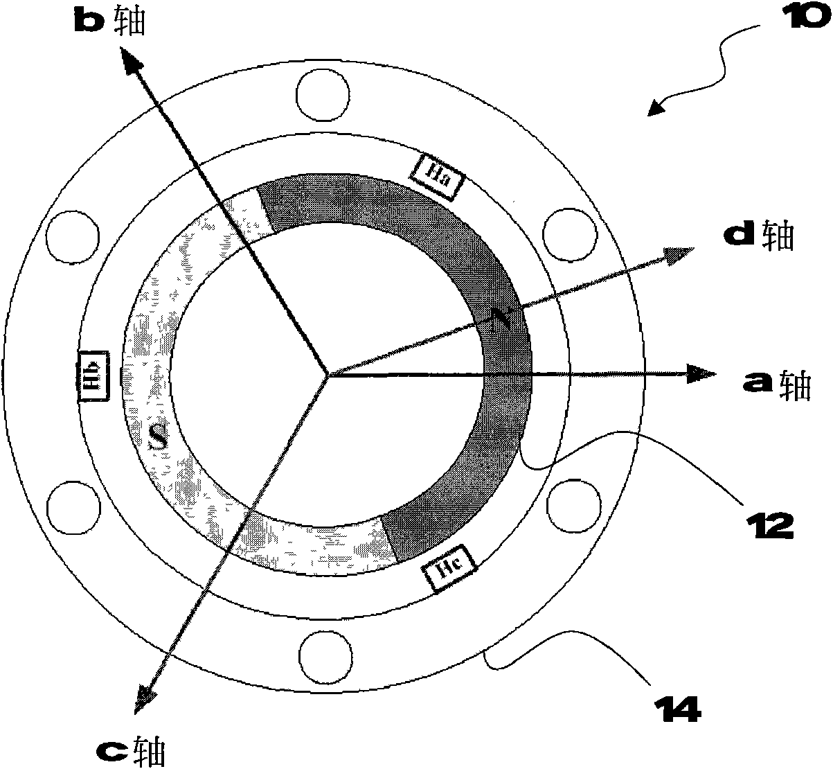
technical field [0001] The present invention relates to a permanent magnet synchronous motor (Permanent Magnet Synchronous Motor; PMSM), in particular, a rotor position detection device and method for a permanent magnet synchronous motor. Background technique [0002] figure 1 A known 2-pole PMSM 10 is shown, which includes a rotor (rotor) 12 and a stator (stator) 14. Accurate control of motor torque (motor torque) requires absolute rotor position information. Known methods generally A resolver, an encoder and a hall sensor are used to sense the rotor position information. However, these sensors will increase the mechanical size and cost of the motor, and reduce the stability of the system. At present, there are many methods to achieve position and speed sensorless control, such as the discussion of the position sensorless operation of brushless permanent magnet machinery proposed by P.P.Acarnley and J.F.Watson (IEEE Trans.Ind.Electron., vol.53, no. 2, pp352-362, April 20...

Claims


Application Information

Patent Timeline
Patent Type & Authority Applications(China)
IPC IPC(8): H02P6/16H02P6/20H02P21/14H02P6/18
Inventor 郑光耀
Owner RICHTEK TECH
Why Eureka
Try Eureka