High-efficiency LED constant current driving circuit

A technology of constant current drive and circuit, applied in the direction of electric lamp circuit layout, electric light source, lighting device, etc., can solve the problems of large number of LED constant current drive circuit components, complex structure, poor stability, etc., and achieve high integration and small size , The effect of reliability improvement

Inactive Publication Date: 2010-08-11
SHANGHAI UNIV
View PDF4 Cites 34 Cited by
  • Summary
  • Abstract
  • Description
  • Claims
  • Application Information

AI Technical Summary

Problems solved by technology

[0014] In view of the deficiencies in the existing LED constant current drive circuit, the purpose of the present invention is to solve the problems of the prior art LED constant current drive circuit, such as the large number of components, large volume, complex str

Method used


Image

  • High-efficiency LED constant current driving circuit
  • High-efficiency LED constant current driving circuit
  • High-efficiency LED constant current driving circuit

Examples


Example Embodiment

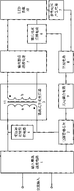
[0033] Embodiment one: as attached figure 2As shown, the LED constant current drive circuit of the present invention includes: input rectification filter circuit 1, switching power supply management chip 2, isolated switching transformer 3, transformer primary clamp circuit 4, output rectification filter circuit 5, output current sampling circuit 6, A reference voltage generation circuit 7 , a comparison circuit 8 , and a photoelectric coupling circuit 9 . The input end of the input rectification filter circuit 1 is connected to the AC mains, and the output end is connected to the primary winding of the isolated switching transformer 3 through the switching power supply management chip 2; the primary clamping circuit 4 of the transformer is connected to the primary winding of the isolated switching transformer 3 The windings are connected in parallel; the input end of the output rectification filter circuit 5 is connected to the secondary winding of the isolated switching tra...

Example Embodiment

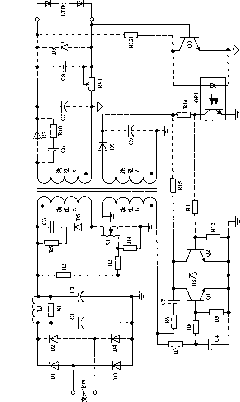
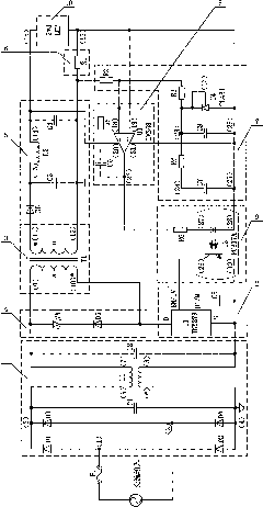
[0035] Embodiment 2: This embodiment is basically the same as Embodiment 1, and the special features are as follows: as attached image 3 As shown, the input rectification filter circuit 1 includes a full-bridge rectifier composed of diodes D1, D2, D3, D4, capacitors C1, C2, common mode inductor L1, the cathode of the diode D2 is connected to the anode of the diode D1, and the diode D4 The cathode of the diode is connected to the anode of the diode D3, and the AC input terminals 1 and 2 are connected to the AC mains; the cathodes of the diodes D1 and D3 are connected as the DC high-voltage output terminal 3 after the rectification of the mains; the anodes of the diodes D2 and D4 are connected as the rectifier The rear ground terminal 4; the DC high voltage output terminals 3 and 4 of the rectifier bridge are respectively connected to the two ends of the capacitor C1 and the two input terminals 5 and 6 of the common mode inductor L1, and the two output terminals 7 and 8 of the c...


PUM


Abstract

The invention relates to a high-efficiency LED constant current driving circuit. The circuit comprises an input rectification filter circuit, a switch power supply management chip, an isolation switch transformer, a primary clamping circuit of the transformer, an output rectification filter circuit, an output current sampling circuit, a reference voltage generation circuit, a comparison circuit and a photoelectrical coupling circuit, wherein the input end of the input rectification filter circuit is connected with commercial AC electricity, while the output end is connected with a primary winding of the isolation switch transformer through the switch power supply management chip; the primary clamping circuit of the transformer is connected in parallel with the primary winding of the isolation switch transformer; the input end of the output rectification filter circuit is connected with the primary winding of the isolation switch transformer, while the output end is connected with LED load; an output current sampling circuit is connected in series with the LED load; the input end of the reference voltage generation circuit is connected with the LED load; and the input end of the comparison circuit is connected with the output current sampling circuit and the reference voltage generation circuit, while the output end is connected with the switch power supply management chip through the photoelectrical coupling circuit. The circuit improves the circuit integration degree, the reliability, the constant current precision and the circuit conversion efficiency.

Description

technical field [0001] The invention relates to a high-efficiency LED driving circuit, in particular to a high-efficiency LED constant-current driving circuit based on an isolated flyback conversion topology, and belongs to the technical field of LED lighting. Background technique [0002] LED has the advantages of high luminous efficiency, long service life, and good stability, and is widely used in the field of lighting. However, the lack of efficiency, reliability and stability of the LED driving circuit has always hindered the reduction of the cost of the LED lighting system, and restricted the service life and popularization of the LED lighting system. [0003] At present, LED drive circuits can be roughly divided into: [0004] (1) Resistance step-down drive mode [0005] (2) Linear regulated / constant current power supply drive mode [0006] (3) Charge pump drive mode [0007] (4) DC-DC conversion drive mode [0008] The resistor step-down LED drive circuit is low...

Claims


Application Information

Patent Timeline
IPC IPC(8): H05B37/02
CPCY02B20/42Y02B20/40
Inventor 刘廷章王世松宋适
Owner SHANGHAI UNIV
Why Eureka
Try Eureka