Soybean milk maker

A soymilk machine and drive motor technology, applied in milk substitutes, beverage preparation devices, household appliances, etc., can solve the problems of slurry residue, difficult to clean, heavy structural machine head, etc., to speed up heating, increase pulping speed, and save energy. The effect of spare parts

Active Publication Date: 2010-08-18
ZHEJIANG SUPOR ELECTRICAL APPLIANCES MFG CO LTD
View PDF5 Cites 3 Cited by
  • Summary
  • Abstract
  • Description
  • Claims
  • Application Information

AI Technical Summary

Problems solved by technology

Therefore, there is a gap between the motor shaft and the spoiler or the curved surface of the spoiler, causing the slurry to enter the spoiler and remain, and it will become moldy or even smelly if it is not cleaned properly
In addition, this technology is a traditional external heating tube, which takes up space, is easily damaged, and is not easy to clean
[0006] In the prior art, the heating element is a heating plate in contact with the bottom of the cup body, or a heating tube fixed on the lid. The heating tube extends into the cup body to heat the slurry, and the motors are all mounted on the top, and the motor shaft The upper coupling is fixed, the upper end of the knife shaft is fixed with the lower coupling, the knife shaft passes through the cup cover and extends into the cup, and the front end of the knife shaft fixes the blade; such a structure machine head is too heavy, the center of gravity is too high, and the working stability is poor; electric heating The distance between the component and the blade is close, and the electric heating tube is easy to coke after the work is completed. It must be cleaned, and there is a danger of hitting the blade by mistake during cleaning.

Method used


Image

  • Soybean milk maker
  • Soybean milk maker
  • Soybean milk maker

Examples


Embodiment 1

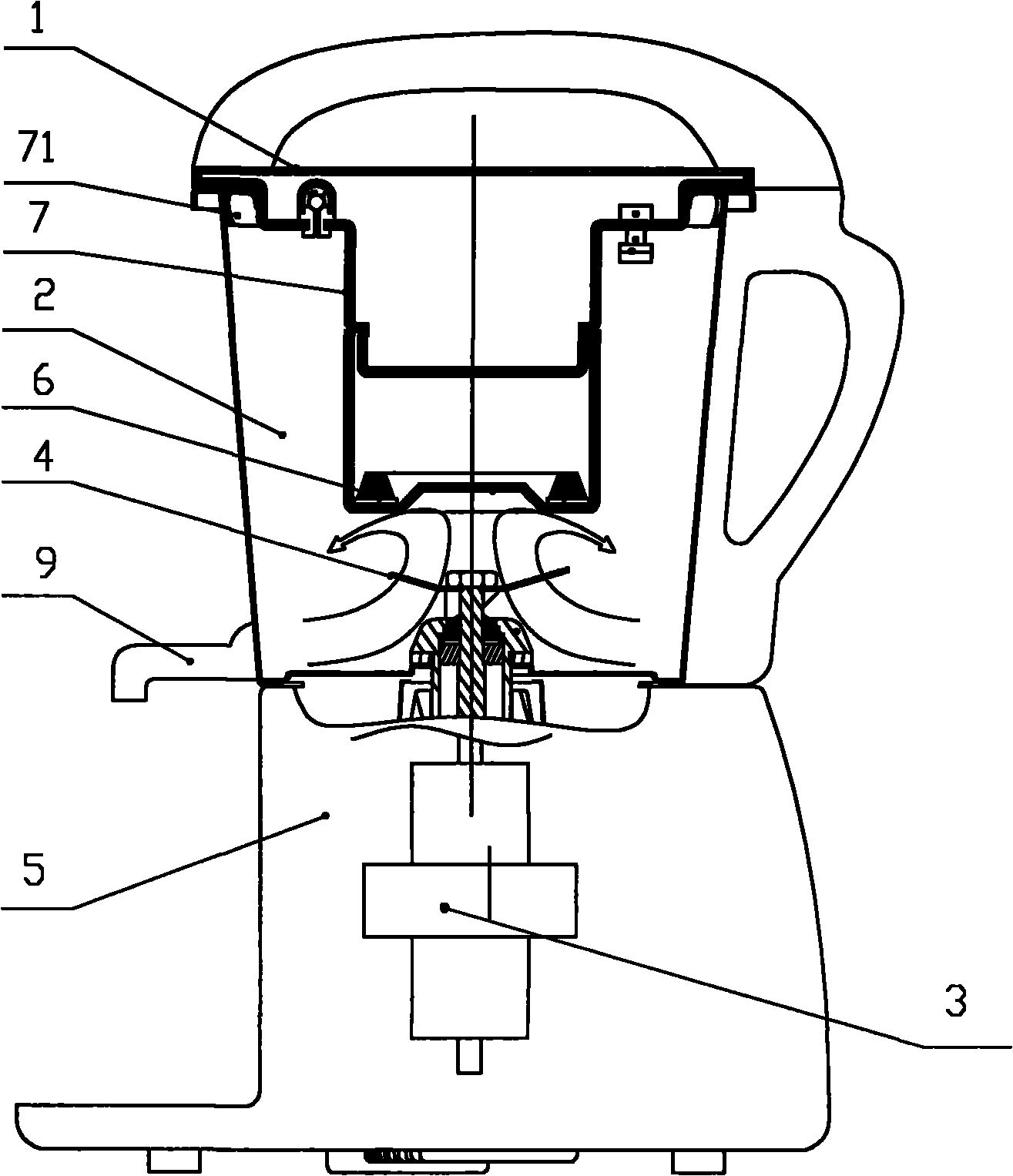
[0047] The soybean milk machine shown in Fig. 1, Fig. 5 and Fig. 6 includes a cup cover 1, a cup body 2, a driving motor 3, a rotating blade 4 and a base 5, wherein the bottom of the cup cover is an inner cover 7, and the inner cover 7 In order to extend from the mouth of the cup to the cup body 2, the bottom surface of the inner cover 7 is a special-shaped surface with a flow guiding effect, the bottom of the inner cover 7 is provided with an electric heating element 6, the motor 3 is arranged in the base 5, and the blade 4 is arranged in the cup body 2 and placed on the inner bottom or below the inner cover 7. The motor shaft of the motor 3 is movably connected with the blade 4 in the cup body through a movable coupling. The blade 4 has a curved surface that makes the slurry roll up and down.

[0048]The electric connection wire of the electric heating element 6 can be electrically connected with the circuit board in the base 5 through the handle. The driving motor 3 and the...

Embodiment 2

[0057] As shown in Figure 2, different from Embodiment 1, the inner cover 7 in this embodiment can be set as a two-section structure, and the upper end is made of plastic material for heat insulation; the section where the electric heating element 6 is installed is made of metal material, preferably It is made of stainless steel, the electric heating element 6 is arranged on the inner bottom of the stainless steel, and the electric heating element 6 is in contact with the surface of the stainless steel. The inner cover of the plastic material is tightly and fixedly connected with the inner cover of the stainless steel material. The inner cover of the stainless steel section is all set below the minimum water level of the soymilk machine to avoid dry burning and ensure safety during use.

Embodiment 3

[0059] As shown in Fig. 3, Fig. 7-Fig. 10, the soybean milk machine in this embodiment is provided with a deflector 8. The blade 4 is located at the center of the wind deflector 8 . As shown in FIG. 8 , flow guide grooves 83 are arranged around the flow guide cover; as shown in FIG. 10 , flow guide holes 82 can also be provided in the flow guide cover. The two are mainly aimed at different materials. When it is necessary to turn back and cut fast, the diversion groove 83 is used. When the material reaches the diversion surface body, it returns through the diversion groove 83. When the pulverized matter is easy to cut and there are many, diversion holes 82 are used; when the material reaches the diversion curved surface, the pressured slurry only makes a small part of the diversion through the diversion holes 82, and the other part will stop for a short time at the upper end, so that Prevent too much material under the blade from affecting the effect of crushing and cutting. ...


PUM


Abstract

The invention discloses a soybean milk maker, belonging to the technical filed of food processing machinery. The soybean milk maker comprises a cup cover (1), a cup body (2), a drive motor (3), a rotating blade (4), an electrical heating element, a control circuit board and a foundation (5), wherein the drive motor and the control circuit are internally arranged on the foundation (5); the cup body (2) is arranged on the foundation (5); the drive motor (3) is connected with a blade through a movable coupling to drive the rotating blade to rotate; and a cutter shaft stretches upwards into the cup body. The soybean milk maker is characterized in that the electrical heating element (6) is arranged in the cup cover, the end part of the cup cover stretches downwards into the cup body, the end face is arranged below 2 / 3 of the height of the cup body, the electrical heating element is connected in the cup cover (1), the rotating blade is arranged at the tail end of the cutter shaft, and the wire of the electrical heating element is connected with the circuit board. The soybean milk maker of the invention has expanded heating range to ensure quick heating speed and more uniform heating, does not generate scorch and over cook, and removes traditional screens, thus saving spare parts and being clean and convenient.

Description

technical field [0001] The invention belongs to the technical field of food processing machinery, and in particular relates to a soybean milk machine without NetEase crushing. Background technique [0002] The traditional soymilk machine is equipped with a net cover on the crushing chamber, so that there are many procedures in the manufacturing process, it is more complicated, and it is not easy to clean, and the cost is also increased. [0003] In recent public documents, there are more public documents of netless soybean milk machines. However, they all add turbulent fluid to the side wall or bottom of the pulping cup, and set different shapes of the cup wall or bottom, so as to achieve the purpose of turbulent flow cutting. When the cup body is a stainless steel cup body, the cup wall provided with spoilers or the cup body provided with baffles will have recessed beading on the surface, which affects the appearance of the soybean milk machine. [0004] Chinese utility m...

Claims


Application Information

Patent Timeline
Patent Type & Authority Applications(China)
IPC IPC(8): A23C11/10A47J31/54
Inventor 蔡才德
Owner ZHEJIANG SUPOR ELECTRICAL APPLIANCES MFG CO LTD
Why Eureka
Try Eureka