

Automatic feeder for punch
An automatic feeding and punching technology, which is used in metal processing equipment, feeding devices, manufacturing tools, etc., can solve the problem that a single feeding does not meet the diverse and multi-specification requirements of the punched workpiece, the safety factor of manual feeding is not high, and the operator's work intensity is high. and other problems, to achieve the effect of reducing product failure rate, avoiding personal injury, and strong practicability
- Summary
- Abstract
- Description
- Claims
- Application Information
AI Technical Summary
Problems solved by technology
Method used
Image

Examples
Embodiment 1
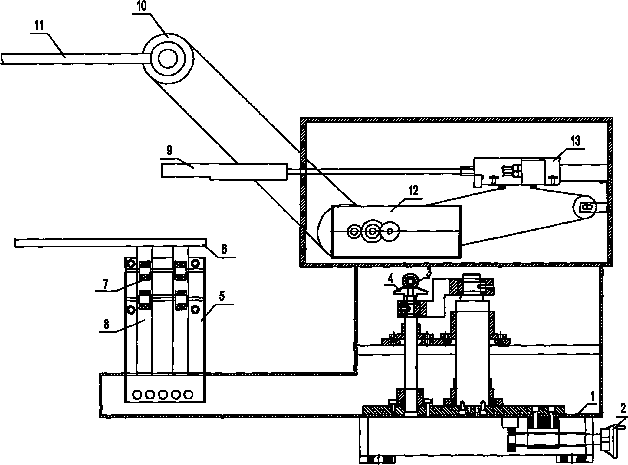
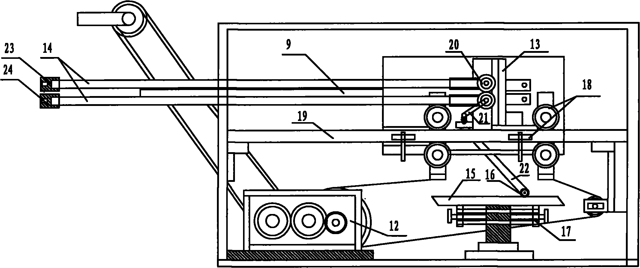
[0029] Figure 1-5 It is the best embodiment of the punch automatic feeder of the present invention,
[0030] Refer to attached figure 1 :
[0031] Punch automatic feeding machine, including frame 1, a frame adjustment mechanism installed at the bottom of frame 1, a stacking plate 6 arranged at the front end of frame 1, a support frame 5 below the stacking plate 6, and a support frame above the stacking plate 6 Push material mechanism and power transmission mechanism. The frame adjustment mechanism realizes the fine adjustment of the position of the frame, including two parts: the horizontal adjustment mechanism and the longitudinal adjustment mechanism. The horizontal lead screw nut; the longitudinal adjustment mechanism is controlled by a pair of vertical upper and lower bevel gears 3 and 4, the frame longitudinal adjustment hand wheel is fixed on the upper bevel gear 3, and the lower bevel gear 4 is fixed on the upper end of the transmission screw. Frame 1 is fixed with...
Embodiment 2
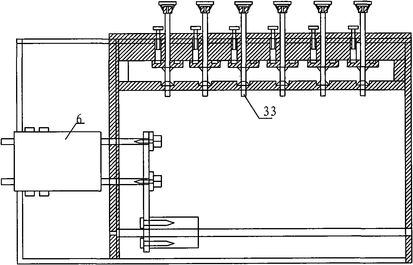
[0042] Refer to attached Figure 6~7 :
[0043] Support frame 5 comprises guide wheel 7, guide rail 8, control lever 33, guide rail fixed plate 27, spring pressing plate 30, spring stay wire 31 and support spring 32, and guide rail fixed plate 27 below is provided with a plurality of support springs 32, and support spring 32 upper ends are fixed Spring pressing plate 30 is arranged, and spring pressing plate 30 is provided with spring backguy 31, and spring backguy 31 other ends are fixed on the control lever 33, and control lever 33 controls spring pressing plate 30 by spring backguy 31 and realizes supporting spring 32 telescopic control.
[0044] Rotate the control lever 33 to adjust the spring backguy 31, the spring backguy 31 drives the spring pressing plate 30 to press down, reducing the number of support springs 32, thereby controlling the size of the applied force, adjusting the lifting of the support frame 5, and indirectly fine-tuning the punched material 29 and the ...
PUM
 Abstract
Description
Claims
Application Information