Rotor wing helicopter

A technology of rotor helicopters and main rotors, applied in rotorcraft, motor vehicles, jet flaps, etc., can solve the problems of complex main rotor structure, accident-prone, and difficult maintenance, and achieve simple structure, high reliability, and convenient maintenance Effect

Inactive Publication Date: 2010-08-18
刘辉
View PDF4 Cites 3 Cited by
  • Summary
  • Abstract
  • Description
  • Claims
  • Application Information

AI Technical Summary

Problems solved by technology

[0003] The technical problem to be solved by the present invention is to install the mechanisms for controlling different flight directions in different positions of the fuselage by splitting the main rotor structure, so as to solve the problem of complex main rotor structure, difficult maintenance, poor stability and accident-prone structure of current rotor helicopters. question

Method used


Image

  • Rotor wing helicopter
  • Rotor wing helicopter
  • Rotor wing helicopter

Examples


Embodiment 1

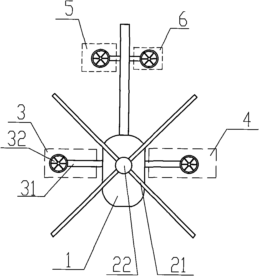
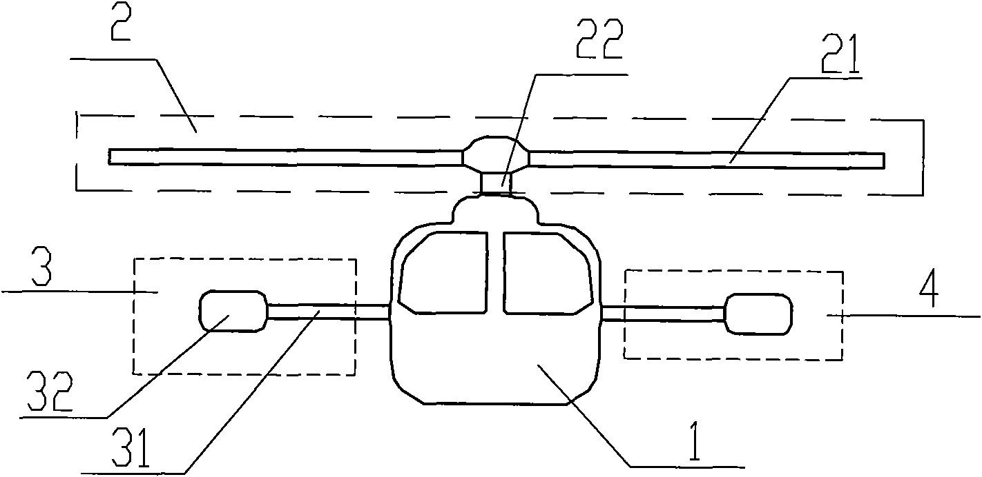
[0014] see figure 1 with figure 2 , a rotor helicopter, including a fuselage 1, a steering control system installed in the fuselage 1, a main engine, a main rotor 2 connected to the main engine through a speed reducer, and a tail rotor. The main rotor 2 provides lift and the power to fly forward. The structure includes a propeller 21 and a transmission shaft 22. The propeller 21 is tilted forward and fixed on the transmission shaft 22. The fixing method can be hinged, seesaw, hingeless or non-hinged. One way in the bearing type is connected, which is the same as the connection way in the prior art. The transmission shaft 22 is connected with the main engine through a speed reducer, the input end of the speed reducer is connected with the main engine to obtain power, and the output end of the speed reducer is connected with the transmission shaft 22 to transmit power to the propeller 21 to make it rotate. The rotor helicopter structure also includes a left-tilt control mecha...

Embodiment 2

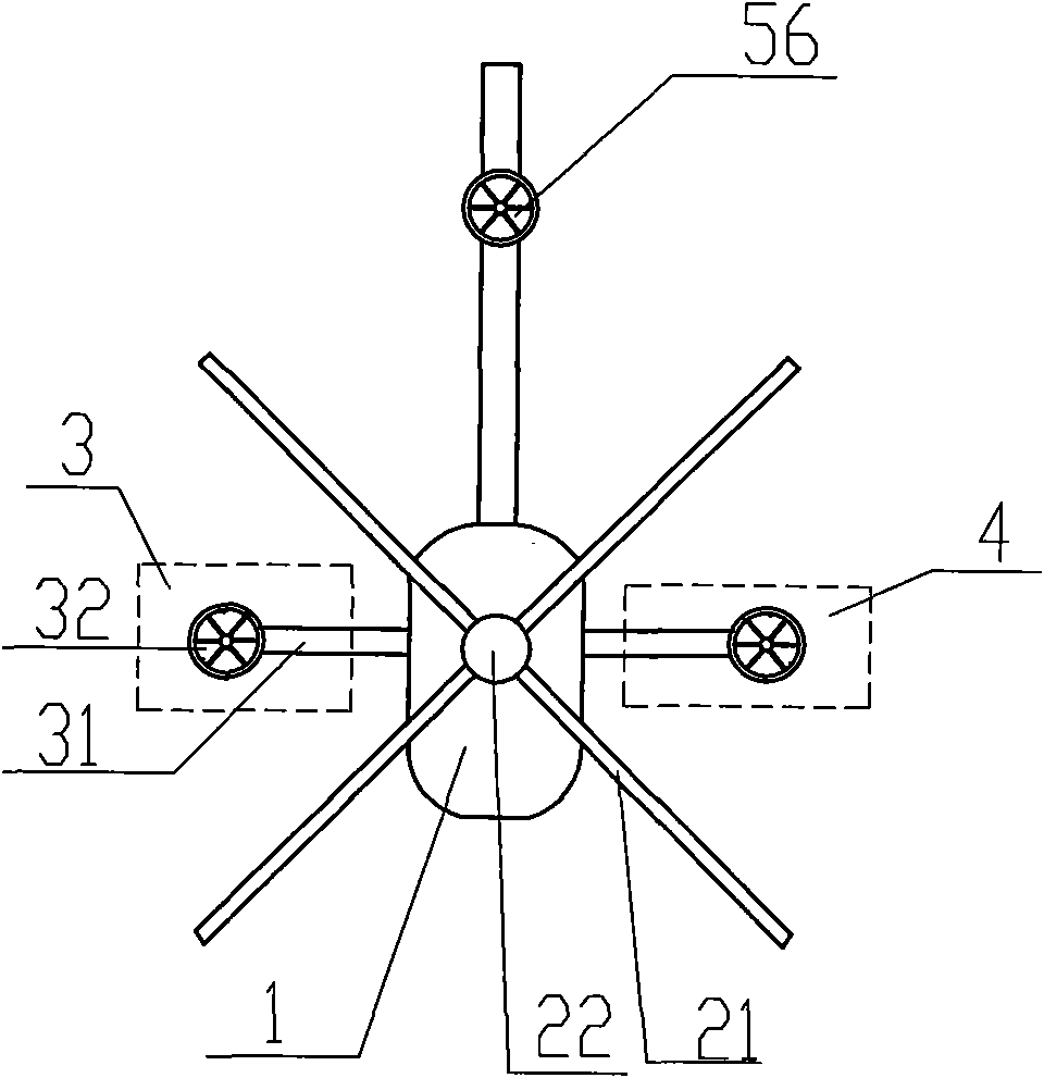
[0018] see image 3 , the difference from Embodiment 1 is that the forward tilt control mechanism and the backward tilt control mechanism are the same forward tilt and backward tilt control mechanism 56, the power unit in which is horizontally arranged at the tail, and the control lines drawn from the steering control system are connected to In the power unit, the power unit adopts a ducted propeller structure. The propeller in this direction control mechanism can rotate forward and also can reverse. Upward thrust is generated during forward rotation, and the aircraft pitches backward; downward thrust is generated during reverse rotation, and the aircraft leans forward.

Embodiment 3

[0020] see Figure 4 with Figure 5 , the difference from Embodiment 2 is that the three direction control mechanisms of the left tilt control mechanism 3, the right tilt control mechanism 4 and the forward and backward tilt control mechanism 56 adopt a high-pressure jet structure, wherein the left tilt control structure 3 includes a structure fixedly connected to the fuselage The support rod 31 on 1, the open end of the support rod 31 is connected with a vertically downward high-pressure gas nozzle 33, the inside of the support rod 31 is provided with a high-pressure gas delivery pipeline, and the high-pressure gas delivery pipeline is connected to the main engine through the high-pressure gas flow controller . The high-pressure gas generated by the operation of the main engine is sent to the high-pressure gas flow direction controller, which includes an air inlet, an exhaust gas discharge port, and several functional outlets. The exhaust outlet is used for normal gas disch...


PUM


Abstract

The invention discloses a rotor wing helicopter, comprising a fuselage, a control system and a main engine installed in the fuselage, a main rotor wing and a stroke oar connected with the main engine through a speed reducer, wherein the main rotor wing structurally comprises a propeller and a transmission shaft; the propeller is fixed to the transmission shaft connected with the main engine through the speed reducer; the rotor wing helicopter further comprises a left-leaning control mechanism and a right-leaning control mechanism that are horizontally, transversely and symmetrically arranged at both sides of the fuselage, a forwards-leaning control mechanism and a backward-leaning control mechanism that are horizontally installed at the stroke oar. The rotor wing helicopter solves the problem that the main rotor wing in the existing rotor wing helicopter has complex structure, hard maintenance, bad stability and high accident ratio.

Description

technical field [0001] The present invention relates to an improved rotor helicopter. Background technique [0002] At present, in the design of the rotor helicopter structure, the design scheme of the main rotor with the tail rotor is the main one. By manipulating the main rotor swash plate to change the movement angle of the main rotor, and then change its stress state, so as to realize the movement of the rotor helicopter in all directions in the air, and at the same time cooperate with the balance of the tail rotor to complete various flight tasks. The role of the tail rotor is to steer and balance the rotation of the main rotor. Relatively speaking, the main rotor of the rotorcraft takes on more tasks. On the one hand, it provides the main power, and on the other hand, it completes the left tilt, right tilt, forward tilt, and backward tilt of the helicopter. Various actions. Therefore, the mechanism of the rotor helicopter main rotor is a multifunctional composite str...

Claims


Application Information

Patent Timeline
Patent Type & Authority Applications(China)
IPC IPC(8): B64C27/06B64C9/38
Inventor 刘辉
Owner 刘辉
Why Eureka
Try Eureka