Air-assisted atomized urea reducing agent spraying controlling system of pump power

An air-assisted and control system technology, which is applied to the electrical control of exhaust treatment devices, exhaust treatment, exhaust devices, etc., can solve the problems of SCR conversion efficiency drop, blockage, etc., and achieve easy industrial application, NOX elimination, and reliable sex high effect

Inactive Publication Date: 2010-08-18
FAW GROUP
View PDF5 Cites 23 Cited by
  • Summary
  • Abstract
  • Description
  • Claims
  • Application Information

AI Technical Summary

Problems solved by technology

However, when the engine is running at a cold start, idling or insufficient combustion stage, the temperature is usually kept below 150°C. At this time, more HC and PM can be generated. These components can block the microscopic pores of the SCR catalyst, resulting in SCR conversion efficiency drops

Method used


Image

  • Air-assisted atomized urea reducing agent spraying controlling system of pump power
  • Air-assisted atomized urea reducing agent spraying controlling system of pump power

Examples


Embodiment 1

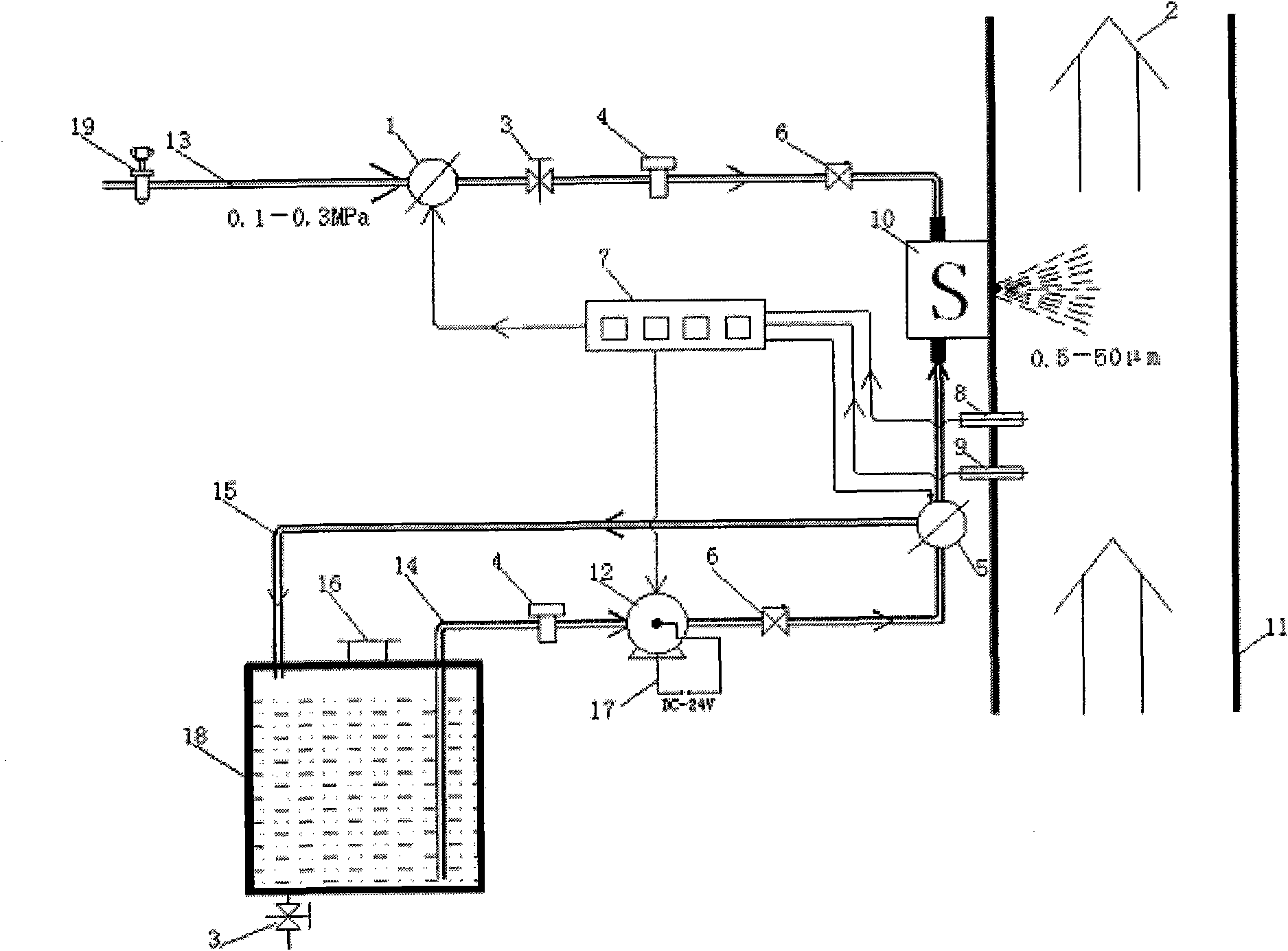
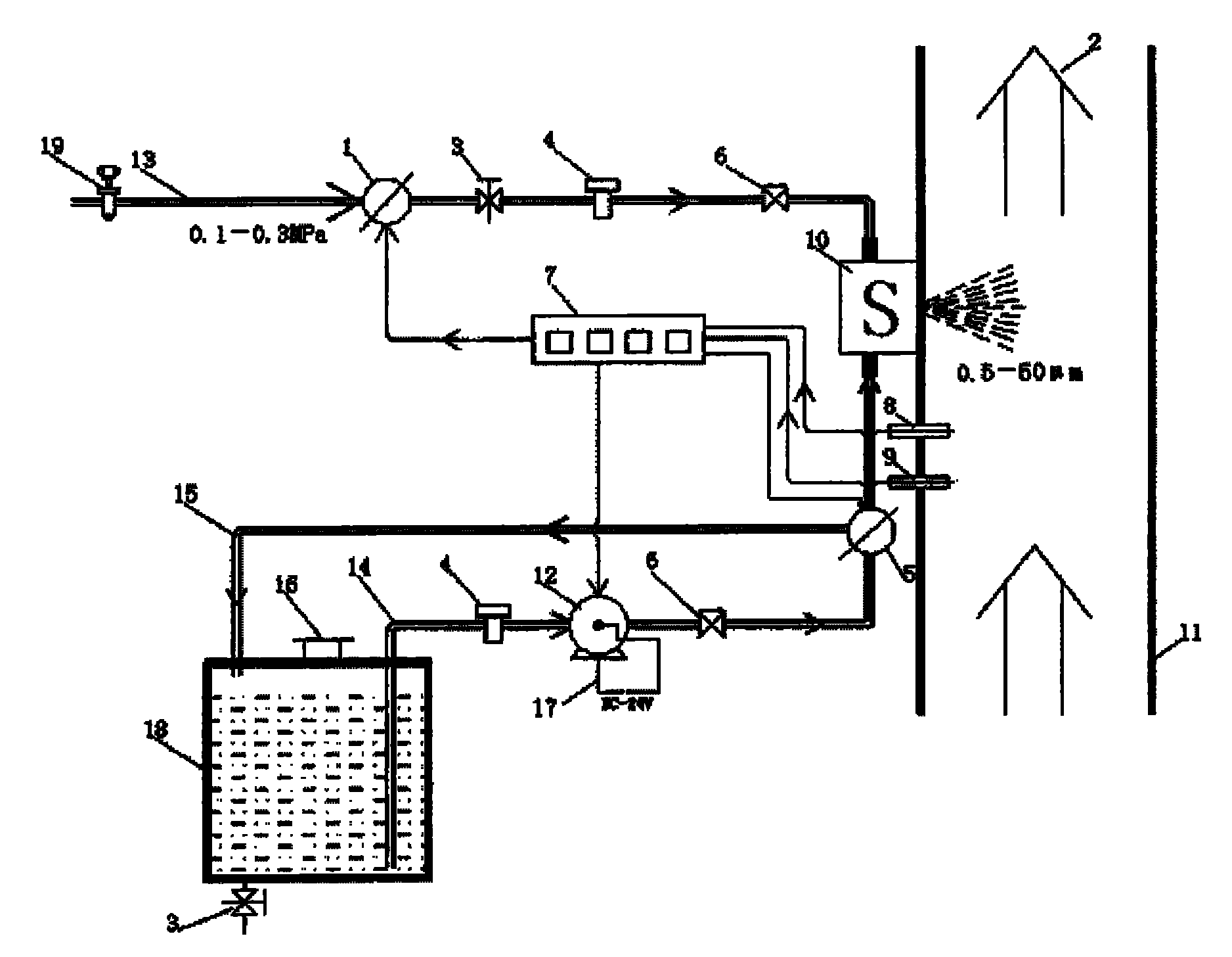
[0026] A stainless steel tube with an inner diameter of 4mm is used as the compressed air main pipe 13. The pressure range of the compressed air main pipe 13 is 0.1Mpa, which is preset by the pressure regulating valve 19. The power source of the compressed air can come from the vehicle-mounted brake air tank; the inner diameter is 4mm. The stainless steel pipe is used as the urea reducing agent delivery pipe 14, the vehicle-mounted 24V DC power supply 17 is used as the power source of the DC urea pump (12), the 24V DC micro gear pump is used as the urea pump 12, and the maximum flow rate at the outlet is 80mL / min; The opening of the flow solenoid valve 5 makes the pressure range of the urea reducing agent flowing to the urea reducing agent nozzle 10 within 0.14Mpa; the opening of the liquid flow solenoid valve 5 is regulated by the signal output by the control unit 7; the input signal of the control unit 7 comes from The industrial temperature sensor 8; the urea reducing agent ...

Embodiment 2

[0028]A nylon tube with an inner diameter of 6mm is used as the compressed air main pipe 13. The pressure range of the compressed air main pipe 13 is 0.3Mpa, which is preset by the pressure regulating valve 19. The power source of the compressed air can come from the vehicle-mounted brake air tank; the inner diameter is 6mm The nylon tube is used as the urea reducing agent delivery pipe 14, the vehicle-mounted 24V DC power supply 17 is used as the power source of the DC urea pump 12, and the 24V DC micro-diaphragm pump is used as the urea pump 12. The maximum flow rate at the outlet end is 150mL / min; The opening of the valve 5 makes the pressure range of the urea reducing agent flowing to the urea reducing agent nozzle 10 within 0.36Mpa; the opening of the liquid flow solenoid valve 5 is adjusted by the signal output by the control unit 7; the input signal of the control unit 7 comes from the industrial temperature sensor 8; the urea reducing agent container 18 is a container w...


PUM


Abstract

The invention relates to an air-assisted atomized urea reducing agent spraying controlling system of pump power. The system is characterized in that the air inlet end of an air compressing main pipe is provided with a pressure adjusting valve; the air outlet end of the air compressing main pipe is communicated with an urea reducing agent nozzle; an urea reducing agent reflowing pipeline is connected with an urea reducing agent container; a cover of the urea reducing agent container is fixed on the urea reducing agent container; the bottom of the urea reducing agent container is connected with a manual liquid switch; an urea reducing agent pipeline and the urea reducing agent reflowing pipeline are communicated with the urea reducing agent nozzle through a liquid flow solenoid valve; and a temperature sensor and a nitric oxide sensor, which are arranged on an exhaust pipe of an engine, are electrically connected with a control unit. The system has low cost which is about equal to 1/2-1/3 of the cost of an imported system, high reliability, and high practical applicability, and is easily industrially applied with domestic resources.

Description

Technical field: [0001] The invention relates to a pump-powered air-assisted atomizing urea reducing agent injection control system, which is applied in the automobile engine industry and meets the environmental protection requirements above Euro 4. Background technique: [0002] The harmful components in automobile engine exhaust are mainly PM, NOX, HC and CO. In the past 2 to 3 years, low-emission engines have become an ideal that people debate, care about, and even aspire to achieve. [0003] The U.S. Environmental Protection Agency (EPA) 2007 emissions regulations require automakers to reduce both particulate (PM) and nitrogen oxide (NOX) pollutants in exhaust gases. This requires considerable skill, and there are no shortcuts to solving this problem. According to the traditional method, the reduction of one kind of pollution will inevitably lead to the increase of another kind of pollution. Automakers appear to be in trouble. [0004] Under the pressure of emission ...

Claims


Application Information

Patent Timeline
Patent Type & Authority Applications(China)
IPC IPC(8): F01N3/20F01N3/24F01N9/00
CPCY02T10/47Y02T10/40
Inventor 张克金王丹魏晓川崔龙张苡铭刘国军董鹤维
Owner FAW GROUP
Why Eureka
Try Eureka