

Automatic handing system of weight and application thereof
A technology for handling systems and weights, which is applied in the field of scale measurement, can solve the problems of manual handling difficulties, increased labor intensity, and increased workload, and achieves the effects of convenient automatic handling, high work efficiency, and small footprint
- Summary
- Abstract
- Description
- Claims
- Application Information
AI Technical Summary
Problems solved by technology
Method used
Image

Examples
Embodiment Construction
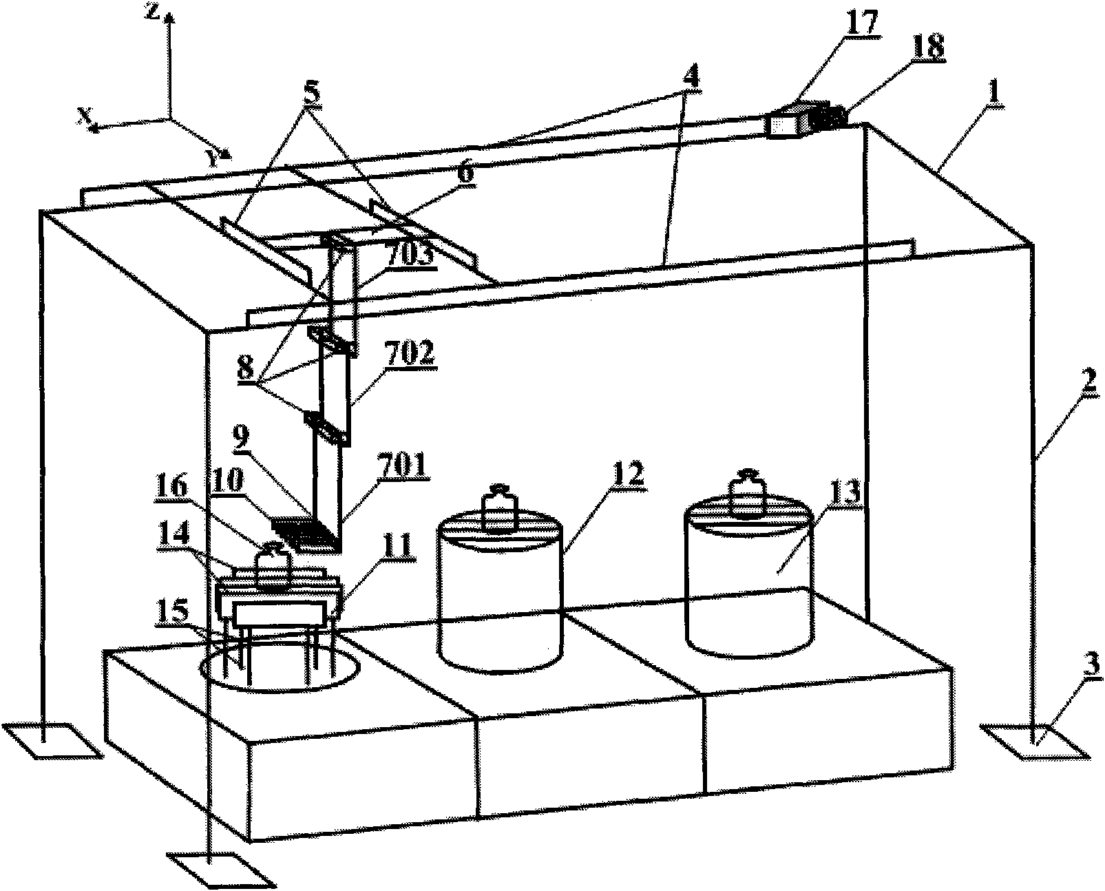
[0028]In the specific implementation, an embodiment adopted by the present invention is to construct a rectangular parallelepiped frame structure 1 with aluminum alloy material, its specification is 3.5m*1.5m*2.8m, and the four supporting legs 2 of the frame pass through the ground Foot bolt 3 is fixed with ground, to reach firm effect. On the two long sides of the frame top, there is respectively a transverse rail 4, on the two long side rails there are short rails 5 perpendicular to the length of 1.5m on the long rails, the distance between the two short rails 5 is 400mm, There are pulleys on both sides of the short track in the transverse track 4, so that the short track 5 can move in parallel along the extending direction of the transverse track 4. There is a 400mm long strip plate 6 perpendicular to the short track 5 on the two short tracks 5, and there are pulleys at both ends of the strip plate 6 in the short track 5, so that the strip plate 6 can extend along the direc...
PUM
 Abstract
Description
Claims
Application Information