Method and equipment for visual detection of visible foreign matters in bottled liquid medicine

A technology for visual inspection of bottled liquids, applied in the direction of optical testing flaws/defects, etc., can solve the problems of swinging centerline, reduce inspection quality, increase false detection rate, etc., to ensure stability, reduce inspection quality, and increase false detection. rate effect

Inactive Publication Date: 2010-08-18
长沙图创机电科技有限公司
5 Cites 36 Cited by

AI-Extracted Technical Summary

Problems solved by technology

However, since the bottle clamping device is composed of two parts, it is very likely that the bottle will be broken when the bottle moves, and the rotating device only drives a part of the clamping device to move. When the bottle rotates at...

Method used

The present invention is aimed at the defect of manual inspection and traditional lamp inspection system, abandons the thought of single-frame image detection, and the present invention has designed a rotating emergency stop detection device, and this device can make the rotation of medicine bottle high-speed then emergency stop, thereby Make the liquid in the bottle and the impurities that may exist in the liquid rotate, use the difference in time and space between t...

Abstract

The invention discloses a method and equipment for the visual detection of visible foreign matters in a bottled liquid medicine. The method comprises the following steps of: (1) obtaining a multi-frame continuous image from a current liquid medicine which is to be detected and is filled in a medicine bottle by using an industrial camera; (2) preprocessing the image: carrying out top-hat morphologic filtering on the obtained image by adopting a 7*7 circular template as a structural element; (3) extracting a moving object; (4) tracking the moving object; and (5) identifying and judging the image. The device comprises a bottle grabbing manipulator used for grabbing the medicine bottle and an image collecting and processing device arranged close to the bottle grabbing manipulator. The method and the device are suitable for detecting the visible foreign matters of a traditional small-capacity bottled liquid medicine and have the advantages of simple realization, good detection effect, high safety and reliability, extensive application range and the like.

Application Domain

Technology Topic

Image

  • Method and equipment for visual detection of visible foreign matters in bottled liquid medicine
  • Method and equipment for visual detection of visible foreign matters in bottled liquid medicine
  • Method and equipment for visual detection of visible foreign matters in bottled liquid medicine

Examples

  • Experimental program(1)

Example Embodiment

[0047] Example 1:
[0048] Aiming at the defects of manual inspection and traditional lamp inspection system, the present invention abandons the idea of ​​single-frame image inspection. The present invention designs a rotating emergency stop detection device, which can make the medicine bottle rotate at a high speed and then stop suddenly, so as to make the bottle inside The liquid and the impurities that may exist in the liquid rotate, and the difference in time and space between the moving and stationary objects in the sequence image is used to distinguish the interference of the bottle body from the foreign body inside the liquid, which overcomes the influence caused by the interference of the bottle body, and finally analyzed by computer The software signals whether the product is qualified.
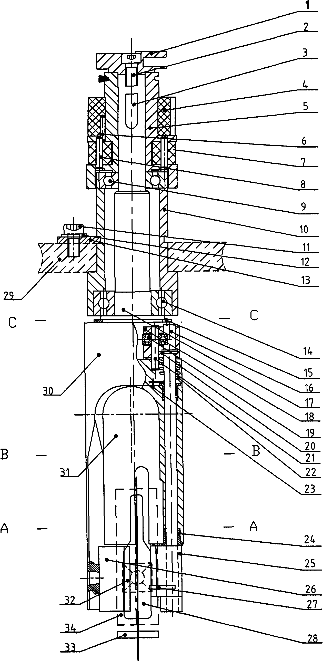
[0049] The main part of the device of the invention is figure 1 As shown, it mainly includes: a bottle grabbing manipulator, an electric drive unit, an image acquisition and processing device set near the manipulator. The detection device must be in a closed light-proof environment during operation.
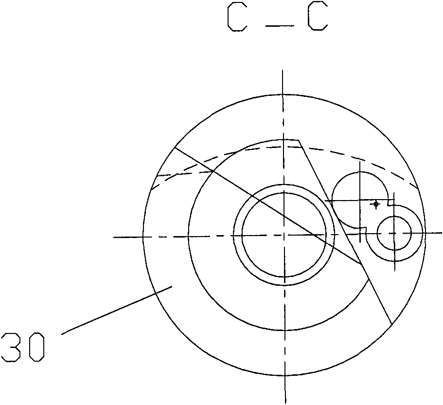
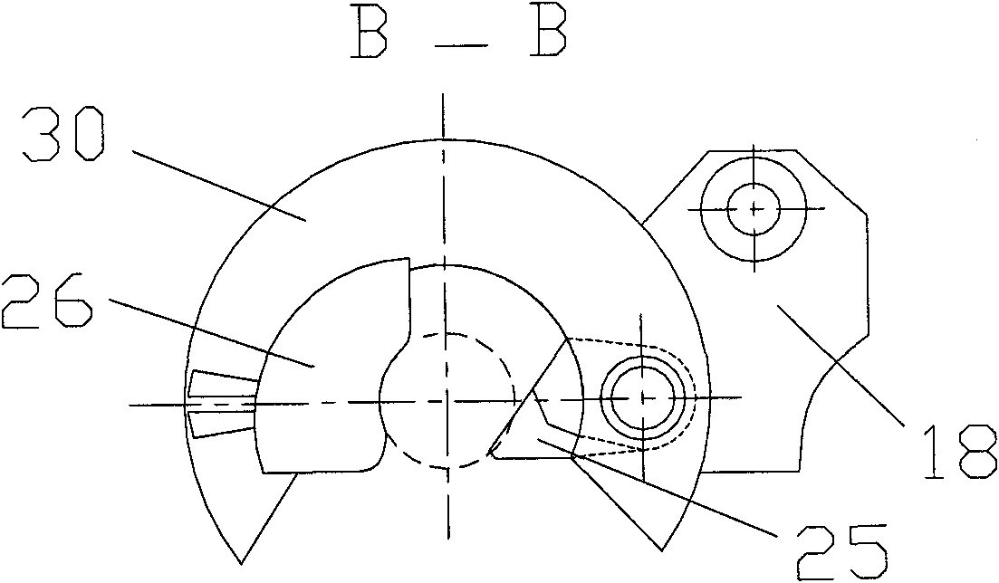
[0050] Such as figure 2 , image 3 , Figure 4 with Figure 5 As shown, the bottle grabbing manipulator includes a guide cylinder and a directional component, and a rotating component arranged from top to bottom; the guide cylinder and the directional component include a guide cylinder 5, a directional roller 7, a directional and dynamic balance weight 4; the upper end of the guide cylinder A positioning end pad 1 is provided; the side wall of the guide cylinder is provided with a directional and dynamic balance weight 4 and a directional roller 7; the rotating part includes a rotating arm 17 and a clamping part 30. The upper end of the rotating arm 17 is connected to the guide cylinder 5, The lower end of the rotating arm 17 is connected to the clamping part 30; the clamping part 30 includes a clamping cylinder 31, a movable arm 25, a static arm 26, and a clamping arm power part; the movable arm is connected to the clamping arm power part through a clamping arm shaft; the rotating part The rotating arm 17 and the guide cylinder are connected with the positioning component and can rotate around it. Among them, the upper part and the middle part of the rotating arm 17 are respectively mounted on the bearing housing 10 through the first deep groove ball bearing 9 and the second deep groove ball bearing 14. The rotating arm 17 is provided with a B-shaped shaft circlip 15 and the bearing The seat 10 is fixedly installed on the rotating platform 29 through the positioning plate 13 using hexagon socket head screws 11 and flat washers 12; the upper end of the rotating arm 17 is fixedly connected with the guide cylinder 5 through the flat key 3, and the positioning end pad 1 is passed through the hexagon socket head screw 2 Connected to the top end of the rotating arm 17, the lower end of the rotating arm 17 is fixedly connected with a clamping member 30, the upper side wall of the guide cylinder 5 is fixedly connected with a directional and dynamic balance weight 4 through a first cylindrical pin 6, and 3 directional rollers 7 are respectively uniformly distributed on the side wall of the guide cylinder 5 by the second cylindrical pin 8 in the circumferential direction and respectively rotate around the second cylindrical pin 8; the clamping member 30 is provided with a clamping cylinder 31, and the lower end of the clamping cylinder 31 is provided with The static arm 26, the clamping cylinder 31 is coaxially provided with a clamping arm shaft 16 rotatable thereon through a composite bearing 24, the lower end of the clamping arm shaft 16 is provided with a movable arm 25, and the side of the movable arm 25 is provided with a positioning pin 27 , The movable arm 25, the positioning pin 27 and the static arm 26 cooperate to clamp the bottle body 28, the upper end of the clamp arm shaft 16 is fixed with a U-shaped block 18 through the third cylindrical pin 20, and the end of the U-shaped block 18 passes through the fourth cylindrical pin 21 is provided with a third deep groove ball bearing 19, the torsion spring 22 is sleeved on the clamp arm shaft 16, one end is fixed to the clamp arm shaft 16, and the other end is fixedly installed on the clamping member 30 through a fifth cylindrical pin 23.
[0051] The image acquisition and processing device includes a high-speed industrial camera 32, a light source, and computer-specific processing software. The light source is composed of a bottom light source 33 and a back light source 34, and is equipped with a strobe device to control the two light source time-sharing trigger points. bright.
[0052] The specific foreign body detection method includes the following steps:
[0053] 1) Use a high-speed industrial camera to obtain multiple continuous images of the current liquid medicine to be detected;
[0054] 2) Image preprocessing: Use the 7×7 circular template as the structural element to perform top-hat morphological filtering on the acquired image to remove various bright and dark noises that are smaller than the structural elements, and get Denoising image;
[0055] 3) Moving target extraction: According to the movement characteristics of the foreign object in the time domain, the new three-frame image difference algorithm is used to extract the moving target in the image. The operation process is: the first frame and the second frame are differentiated Processing, the second frame and the third frame are differentially processed, and then two binary images are obtained through binarization, and the two binary images are logically ANDed at each pixel position to obtain a symmetric difference result binary image ;
[0056] 4) Moving target tracking: Due to interference in foreign body imaging, the liquid medicine foreign body meets the continuity and consistency of the motion trajectory in the short sequence of frames, and the noise interference does not have the above characteristics. In order to achieve the purpose of filtering noise and detecting, The method of tracking moving targets in short sequence frames realizes foreign body detection. The tracker in this method uses the traditional Meanshift tracker.
[0057] 5) Image recognition and judgment: The target motion trajectory is obtained through the tracking result, and the continuity and directionality of the target trajectory are used to distinguish foreign objects and noise targets, so as to finally judge whether the current liquid medicine is qualified. Because the direction of movement of the bubble is upward from the bottom of the bottle, the movement direction of the foreign body is opposite to that of the bubble due to gravity. In addition, the movement of the two types of objects is continuous, and the noise is generated randomly. Therefore, follow the continuous trajectory of the target. Distinguish between foreign objects and noisy targets based on the characteristics and directionality recognition.
[0058] The step 2) is:
[0059] Assuming that the grayscale function of the image is f(x, y), the structure element is B(x, y), and (x, y) are the pixel coordinates, the four basic operations are defined as follows:
[0060] Corrosion: (fΘB)(x,y)=min{f(x+i,y+j)-B(i,j)|(x+i,y+j)∈D f;(I,j)∈D B };
[0061] Expansion: (f⊕B)(x,y)=max{f(x-i,y-j)+B(i,j)|(x-i,y-j)∈D f;(I,j)∈D B };
[0062] Open operation: fοB=(fΘB)⊕B;
[0063] Close operation: f·B=(f⊕B)ΘB;
[0064] In the formula, D f And D B Are the domains of functions f and B,
[0065] Introduce the top hat transform filter operator: Hat(f)=f-(fοB);
[0066] In the formula (fοB) is that the structure element B performs the gray-scale opening operation on the image f, and the 7×7 circular template is selected as the structure element to perform the top-hat morphological filtering of the original image to obtain the image containing foreign objects and bubbles, that is, remove Noisy image.
[0067] The step 3) is:
[0068] For the denoised image, select the three-frame sequence image f(x, y, t k-1 ), f(x, y, t k ) And f(x, y, t k+1 ) Calculate the absolute difference grayscale images of two adjacent frames:
[0069] D (k-1, k) (x,y)=|f(x,y,t k-1 )-f(x, y, t k )| (4)
[0070] D (k, k+1) (x,y)=|f(x,y,t k+1 )-f(x, y, t k )| (5)
[0071] Among them, the images f are all preprocessed images, for D (k-1, k) (x, y) and D (k, k+1) (x, y) are thresholded respectively, and two binary images B are obtained by binarization (k-1, k) (x, y) and B (k, k+1) (x, y). Will B (k-1, k) (x, y) and B (k, k+1) (x, y) Perform a logical AND operation at each pixel position to obtain a binary image D of the symmetric difference result S(k) (x, y), the calculation formula is as follows:
[0072]
[0073] After experimental analysis, the article uses the frame difference method to detect moving targets, and the detection effect of this method is ideal.
[0074] Such as figure 1 , figure 2 , image 3 , Figure 4 , Figure 5 , Image 6 As shown, the working process of the present invention:
[0075] The working principle of the visible foreign body detection device for bottled liquid medicines is: the principle of using the bottle clamping manipulator to grasp the bottle-rotate-emergency-stop-tracking and shoot multi-frame product images to detect whether the bottled liquid contains visible foreign objects, and to check the processing results of the image detection organization Products are classified. The specific working process is: the bottle clamping manipulator clamps a bottle to be tested from the bottle feeding device and rotates at a reasonable speed at a reasonable speed around the central axis of the rotary table until the bottle to be tested passes the bottle rubbing device, the brake device, and the tracking and shooting device Reach the bottle discharge device; the bottle rubbing device drives the bottle body to rotate at a uniform acceleration around its axis until the speed reaches the set value, and drives the bottle body to maintain the set speed to continue to rotate at a constant speed; the brake device rotates the bottle body in a short time Perform rapid braking, and use high-brightness LED red point light source to emit visible light from the bottom of the bottle to the bottle. At the same time, after the braking device is activated, a camera fixed on the workbench is used to perform Take multiple photos; then send multiple images to the image processing system, and detect whether there are foreign objects in the liquid through mutual comparison of multiple images and image processing; when the detection result shows that the liquid contains foreign objects, the control system will give out a defective signal; When the test result shows that there is no foreign matter in the liquid, the control system gives a signal of qualified product.
[0076] The function of the bottle clamping manipulator of the present invention in the visible foreign matter detection device for bottled liquid medicines is to clamp the bottle body and take it from the bottle feeding device to complete acceleration, braking, photographing, and reach the bottle outlet device. The working process is as follows:
[0077] 1. Bottle grabbing process: When the external top block mechanism pushes the U-shaped block 18 on the bottle grabbing manipulator, the action of the U-shaped block 18 drives the arm shaft 16 in the manipulator to rotate, and when the arm shaft 16 rotates to a certain position At this time, the boom 25 is fully opened, and the bottle body enters the clamping cylinder 31.
[0078] 2. Clamping process: After the bottle body enters the clamping barrel 31, the U-shaped block 18 on the clamping manipulator is separated from the top block mechanism, so that the clamping arm shaft 16 returns to the front of the bottle under the reaction force of the torsion spring 22 At this time, the bottle body is firmly secured in the clamping cylinder 31. Due to the reasonable design of the static arm 26 and the movable arm 25 molds of the manipulator and the function of the torsion spring 22, the pressure on the bottle body 28 during the clamping process can be fully ensured that the pressure is appropriate and uniform, thereby ensuring that the bottle will not be broken.
[0079] 3. High-speed rotation process: After the manipulator grips the bottle body 28, the manipulator rotates around the central axis of the rotary table at a reasonable speed at a uniform speed until the tested bottle body reaches the bottle rubbing device. At this time, the rubbing device acts on the positioning end. The pad 1 drives the manipulator to perform friction acceleration, and the bottle body 28 rotates around its axis until the rotation speed reaches a set value, and drives the bottle body 28 to maintain the set rotation speed to continue rotating at a constant speed.
[0080] 4. Braking and image acquisition and detection process: When the manipulator completes high-speed rotation, the manipulator enters the braking area, and the braking device acts on the positioning pad 1 in a short time to quickly brake the rotating bottle body 28, and pass the high speed. Brightness LED red point light source and LED red surface light source emit visible light from the bottom and side of the bottle body 28 to the bottle body in time sharing. At the same time, after the brake device is activated, a camera 32 fixed on the workbench faces the side of the bottle body. The bottle body 28 takes multiple photos; then multiple images are sent to the image processing system, through the mutual comparison of multiple images and image processing to detect whether the liquid contains foreign matter; when the detection result shows that the liquid contains foreign matter, the control system gives Defective product signal; when the test result shows that there is no foreign matter in the liquid, the control system will give a qualified product signal.
[0081] 5. Bottle discharging process: After the manipulator grips the bottle body to complete the inspection process, the manipulator enters the bottle discharging area. There are two discharging stations in the bottle discharging area, one is for qualified products and the other is for rejecting bottles of defective products. According to the above image detection results, the two bottle discharging stations respectively trigger the corresponding electromechanical devices to push the U-shaped block 18 on the manipulator. The action of the U-shaped block 18 drives the arm shaft 16 in the manipulator to rotate. When rotating to a certain position, the boom 25 is fully opened, and the bottle 28 enters the qualified product conveyor belt or the defective product conveyor belt.

PUM

no PUM

Description & Claims & Application Information

We can also present the details of the Description, Claims and Application information to help users get a comprehensive understanding of the technical details of the patent, such as background art, summary of invention, brief description of drawings, description of embodiments, and other original content. On the other hand, users can also determine the specific scope of protection of the technology through the list of claims; as well as understand the changes in the life cycle of the technology with the presentation of the patent timeline. Login to view more.

Similar technology patents

Classification and recommendation of technical efficacy words

  • Simple structure
  • Improve detection quality

Microlithographic projection exposure apparatus

InactiveUS20050068499A1Simple structureReliable and low-maintenance operationProjectorsPhotomechanical exposure apparatusCamera lensPhysics
Owner:CARL ZEISS SMT GMBH
Why Eureka
Try Eureka