Frequency self-correction phase lock loop adopting bonding wire as electric inductance of oscillator
A self-calibration, phase-locked loop technology, applied in the field of phase-locked loops, to achieve the effect of reduced area, faster speed, lower power consumption and phase noise
- Summary
- Abstract
- Description
- Claims
- Application Information
AI Technical Summary
Problems solved by technology
Method used
Image
Examples
Embodiment Construction
[0036] The specific implementation manners of the present invention will be described in further detail below in conjunction with the accompanying drawings and examples. The following examples are used to illustrate the present invention, but are not intended to limit the scope of the present invention.
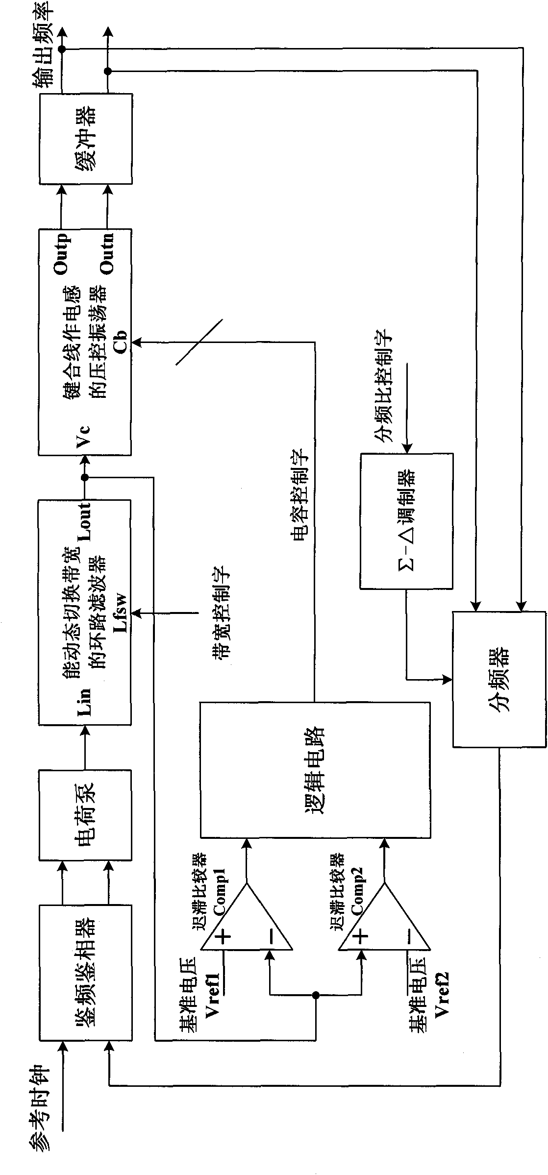
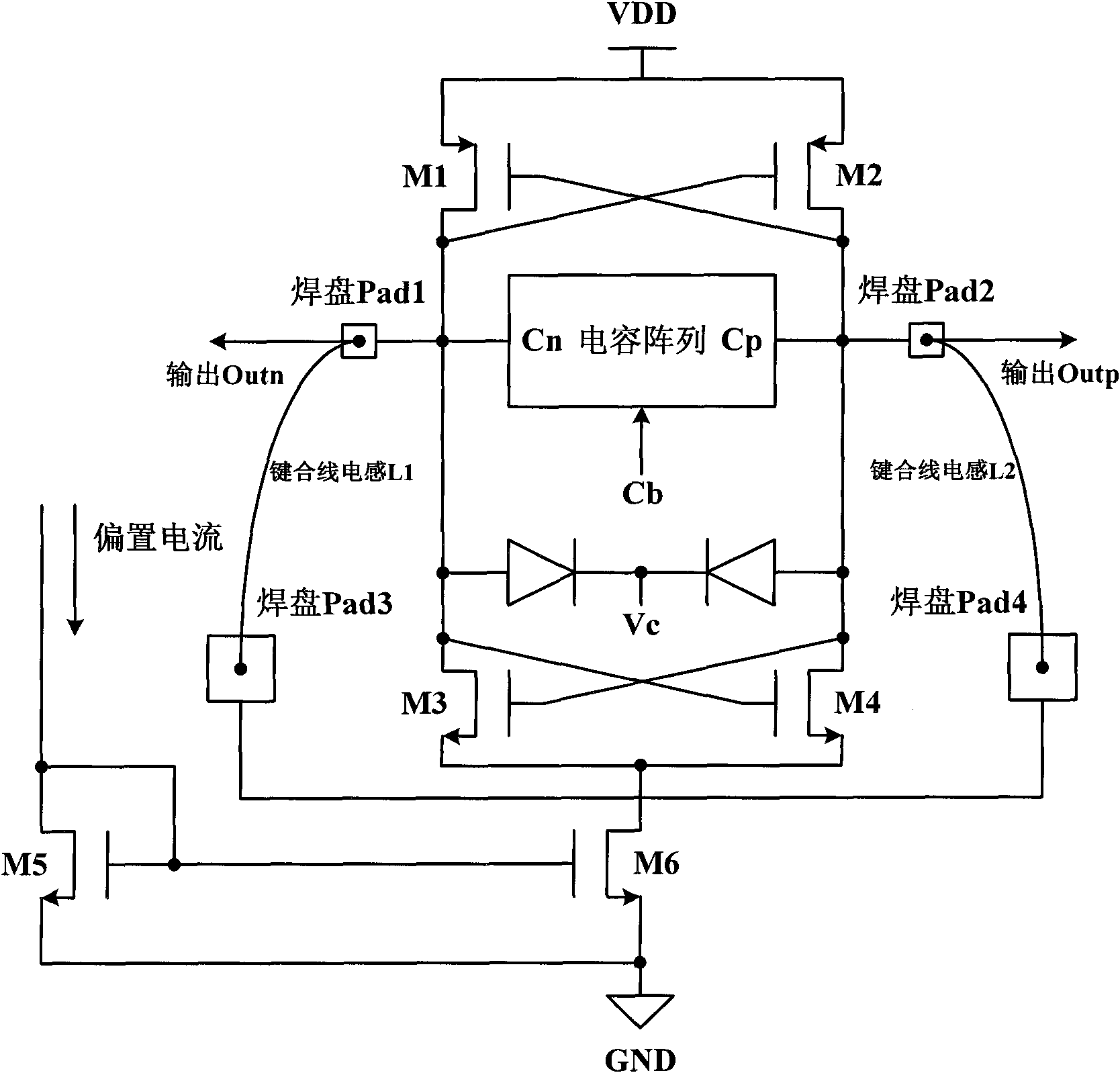
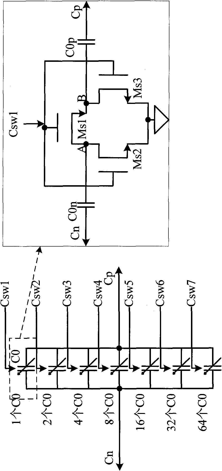
[0037] The block diagram of the frequency self-correcting phase-locked loop circuit using the bonding wire as the oscillator inductance in the embodiment of the present invention is as follows figure 1As shown, the output terminal of the frequency and phase detector is connected to the input terminal of the charge pump, the output terminal of the charge pump is connected to the input terminal of the loop filter capable of dynamically switching bandwidth, and the output terminal of the loop filter capable of dynamically switching bandwidth is connected to The control voltage input terminal of the voltage-controlled oscillator using the bonded wire as the inductor, the output t...
PUM
 Abstract
Description
Claims
Application Information
 - R&D
- Intellectual Property
- Life Sciences
- Materials
- Tech Scout
- Unparalleled Data Quality
- Higher Quality Content
- 60% Fewer Hallucinations
Browse by: Latest US Patents, China's latest patents, Technical Efficacy Thesaurus, Application Domain, Technology Topic, Popular Technical Reports.
© 2025 PatSnap. All rights reserved.Legal|Privacy policy|Modern Slavery Act Transparency Statement|Sitemap|About US| Contact US: help@patsnap.com


