Hybrid vortex rail braking system

A braking system and hybrid technology, applied in electric braking systems, asynchronous inductive clutches/brakes, electric vehicles, etc., can solve the problem that the natural eddy current braking system cannot work, the excitation power is too large, and the weight of the train is affected. and other problems, to achieve the effect of simple structure, energy saving, increased reliability and safety

Inactive Publication Date: 2010-08-25
ZHEJIANG UNIV
View PDF4 Cites 14 Cited by
  • Summary
  • Abstract
  • Description
  • Claims
  • Application Information

AI Technical Summary

Problems solved by technology

First of all, although the pressure release can be used to ensure that the air cylinder operates when the air system fails, when the circuit fails, the loss of excitation will directly lead to the loss of braking force
To this end, ICE3 installed a large-capacity nickel-cadmium battery as a backup power supply, and additionally installed an additional friction braking system as a cold backup redundancy, but the weakness of the eddy current track braking system itself already exists, and affects the lightness of the train. Quantify
Secondly, when the power supply is cut off when the train is parked, the natural eddy current braking system cannot work
In addition, the excessive excitation power and the resulting heat are also problems to be solved

Method used


Image

  • Hybrid vortex rail braking system
  • Hybrid vortex rail braking system
  • Hybrid vortex rail braking system

Examples


Embodiment Construction

[0022] The present invention will be further described below in conjunction with drawings and embodiments.

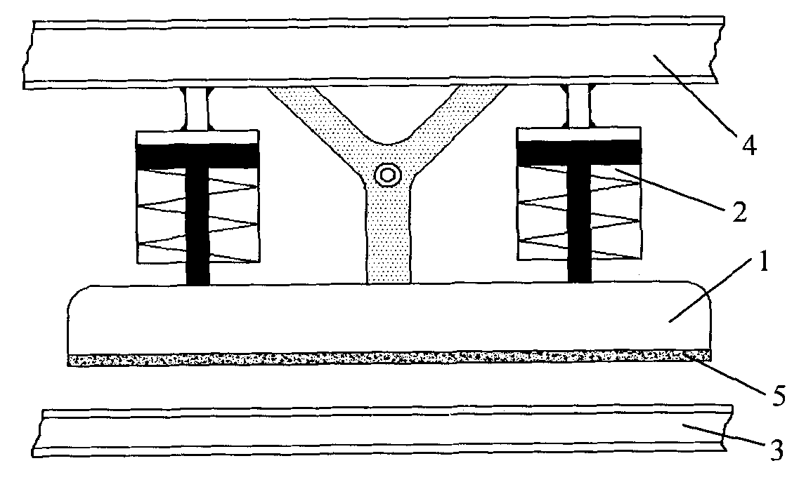
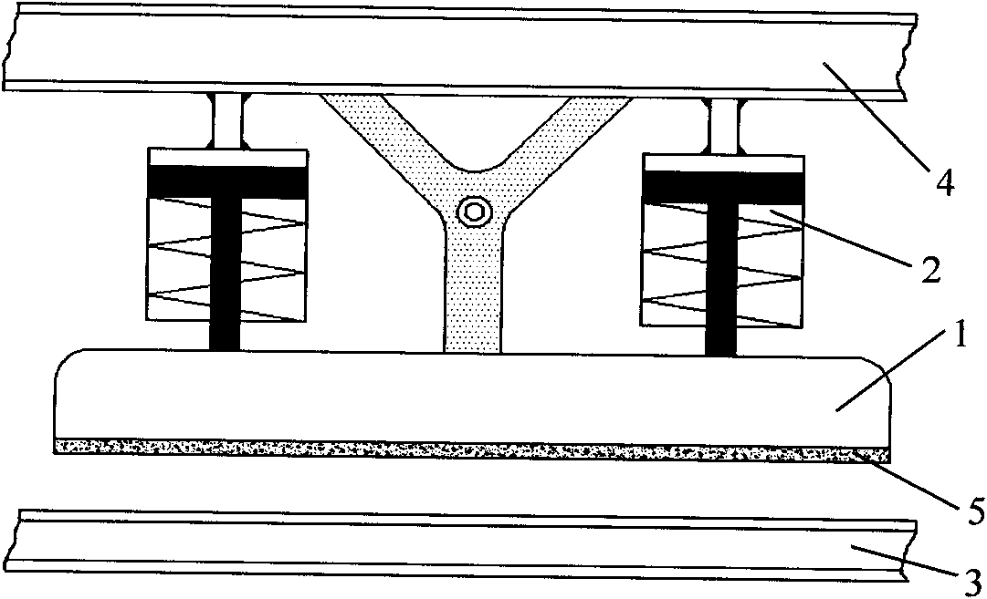
[0023] As shown in Figure 1, the present invention installs lifting air cylinders 2 symmetrically on both sides of the Y-shaped rotating fulcrum between the bogie frame side beam 4 and the brake magnetic system 1, and the air brake lifting system is connected with the two lifting air cylinders respectively. 2 connection, the piston rods of the two lifting air cylinders 2 are connected to the brake magnetic system 1, the rodless chambers of the two lifting air cylinders 2 are connected to the bogie frame side beam 4, and the wear plate 5 on the bottom surface of the brake magnetic system 1 faces the rail 3.

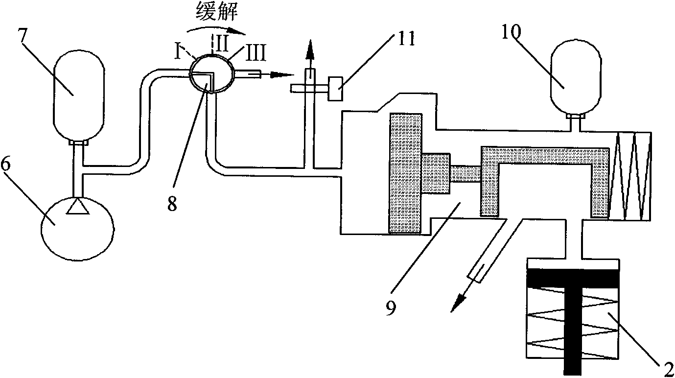
[0024] As shown in Figure 2 and Figure 3, the air brake lifting system includes a lifting air cylinder 2, an air compressor 6, a main air cylinder 7, a brake valve 8, a control valve 9, an auxiliary air cylinder 10 and an emergency brake valve 11 The air compressor ...


PUM


Abstract

The invention discloses a hybrid vortex rail braking system. In the technical scheme, lifting air cylinders are symmetrically arranged on both sides of a Y-shaped rotating pivot between a side frame of a truck frame and a magnetic system of a brake, an air braked handling system is respectively connected with the two lifting air cylinders, the piston rods of the two lifting air cylinders are connected with the magnetic system of the brake, the rod-free cavities of the two lifting air cylinders are connected with the side beam of the truck frame, and a wear plate on the bottom surface of the magnetic system of the brake is arranged to be opposite to a rail. The invention can control the power and the deceleration process through positive excitation of the exciting coil and regulation of the exciting current, thereby achieving the effect of actively controlling the deceleration. The magnetic attraction between the magnetic system of the brake and the rail can be reduced through reverse excitation of the exciting coil, thereby facilitating the lifting of the magnetic system of the brake. Simultaneously, the invention has the advantages of simple structure, energy conservation, high reliability, light weight and the like, and not only can be applied in high-speed railways, but also has broad application prospects in maglev trains, urban rail transits and other fields.

Description

technical field [0001] The invention relates to a rail braking system, in particular to a hybrid eddy current rail braking system. Background technique [0002] The shortage of railway transport capacity has become one of the main contradictions restricting the development of my country's economic construction. High-speed railway has become the basic trend of railway development and the basic guarantee of national modernization due to its advantages of large transportation capacity, safety and comfort, all-weather transportation, environmental friendliness and sustainability. According to the "Medium and Long-Term Railway Network Planning", the construction mileage of my country's high-speed railway will reach 7,000 kilometers during the "Eleventh Five-Year Plan" period, and will reach 18,000 kilometers by 2020. [0003] Braking technology is one of the nine key technologies of high-speed trains. As we all know, the braking power is proportional to the cube of the train spe...

Claims


Application Information

Patent Timeline
Patent Type & Authority Applications(China)
IPC IPC(8): B60L7/28H02K49/04
CPCY02T10/641Y02T10/64
Inventor 方攸同夏长亮马吉恩王立天孟亮姚缨英
Owner ZHEJIANG UNIV
Why Eureka
Try Eureka