Heating station for implementing trans-season heat storage, cooling-storage adopting combined pump technology

A combined pump and cross-seasonal technology, which is applied in the field of thermal stations for central heating, can solve the problems of commercial application of heat storage and heat supply across seasons.

Inactive Publication Date: 2012-05-23
邢玉明
View PDF0 Cites 0 Cited by
  • Summary
  • Abstract
  • Description
  • Claims
  • Application Information

AI Technical Summary

Problems solved by technology

Due to excessive concerns about construction difficulty and investment risks, there has been no in-depth research on the use of existing materials to achieve cross-season heat storage. Until now, cross-season heat storage has not been commercially applied.

Method used


Image

  • Heating station for implementing trans-season heat storage, cooling-storage adopting combined pump technology
  • Heating station for implementing trans-season heat storage, cooling-storage adopting combined pump technology
  • Heating station for implementing trans-season heat storage, cooling-storage adopting combined pump technology

Examples


Embodiment 1

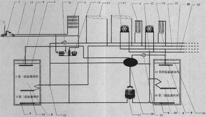
[0036] The combined pump 14 decompresses the hot liquid 8 of the main heat network 13 and introduces it into the inner pipe network, and pumps the equivalent liquid 8 of the inner pipe network to the main heat network 13 . Build a heat storage and heat preservation liquid storehouse with a volume of 1 million cubic meters near the combined pump 14 or the main heat network heat exchanger 39, the part whose upper layer temperature is higher than 60°C is the first heat preservation liquid storehouse 2, and the lower layer temperature is lower than 60°C The part is the second heat preservation liquid storehouse 3; the cold storage heat preservation liquid storehouse with a volume of 1,000,000 cubic meters is set, the part whose upper layer temperature is higher than 15°C is the fourth heat preservation liquid storehouse 19, and the part whose lower layer temperature is lower than 15°C is The third heat preservation liquid storehouse 18 . The excess hot liquid 8 in the internal pip...

Embodiment 2

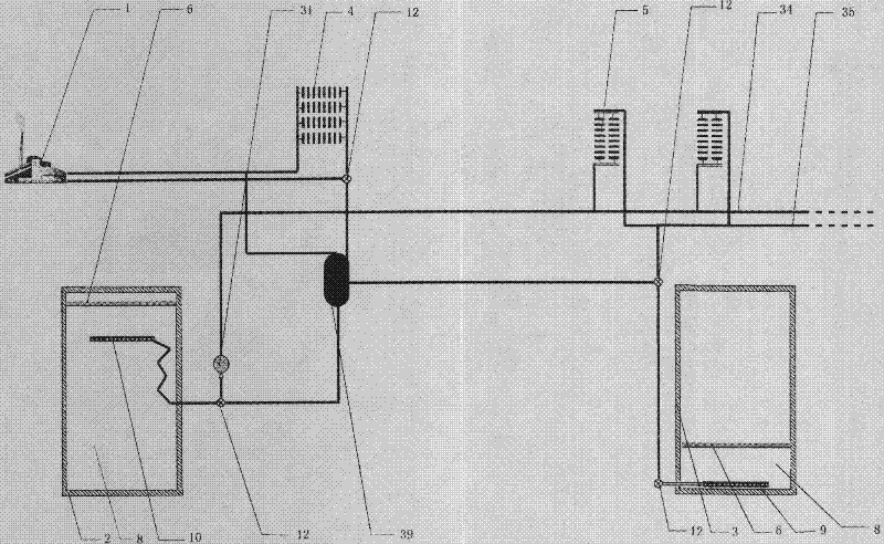
[0040] The main heat network heat exchanger 39 is used to transfer the heat energy of the main heat network 13 to the inner pipe network. The first heat preservation liquid storehouse 2 and the second heat preservation liquid storehouse 3 with a volume of 500,000 cubic meters are respectively constructed in sub-pools near the main heat network heat exchanger 39, and the surplus heat liquid 8 of the inner pipe network is injected into the first heat preservation liquid storehouse 2, At the same time, the hot liquid return pipe 35 extracts an equivalent amount of liquid 8 from the second heat preservation liquid storehouse 3 . External heat source 1 is the waste heat of cooling water and waste heat of flue gas recovered by a steel plant. Heat users 5 include heating radiators and centralized hot water supply devices. When the heat supply of the hot liquid 8 in the internal pipe network is insufficient, the hot liquid 8 in the first thermal insulation liquid storage 2 is extract...

Embodiment 3

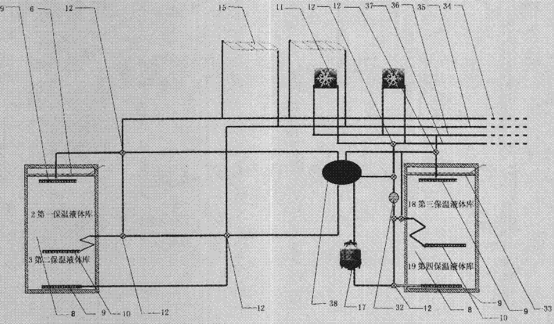
[0043]Build a heat storage and thermal insulation liquid storage with a volume of 300,000 cubic meters, the part whose upper layer temperature is higher than 60°C is the first thermal insulation liquid storage 2, and the part whose lower layer temperature is lower than 60°C is the second thermal insulation liquid storage 3; construction A cold-storage heat preservation liquid storehouse with a volume of 300,000 cubic meters, the part whose upper temperature is higher than 15°C is the fourth heat preservation liquid storehouse 19, and the part whose lower floor temperature is lower than 15°C is the third heat preservation liquid storehouse 18. Three liquid distributors 9 are respectively arranged in the two pools, one at the top and one at the bottom, and a liquid distributor 10 that can move up and down in the middle. The internal heat source 15 feeds the hot liquid 8 into the hot liquid pipe 34 and draws an equal amount of liquid 8 from the hot liquid return pipe 35 at the sam...


PUM


Abstract

The invention discloses a heating station, a unipump and an overcooling-method ice slurry generating device. The conventional heating station does not have thermal storage function and cannot store or utilize surplus heat energy of a main heat network and an inner heat source, cannot store or utilize climate heat energy and climate cold energy, cannot utilize discontinuously stable industrial waste heat to supply heat or cold, and cannot eliminate fluctuation of the thermal load of the heat source caused by requirement fluctuation. On the basis of the conventional heating station, a heat insulating liquid house is arranged to store surplus heat energy or cold energy to form a continuous and stable heat source so as to improve the utilization rate of the heat source, expand the range of utilizable heat sources, and eliminate fluctuation of the heat source due to the change of the thermal load. The invention also discloses the unipump. The moment converted by a depressurization pump drives a booster pump, so that the main heat network directly supplies heat to users on the premise of not improving circular power consumption; and the same principle is applied to the ice slurry generating device, and the ice slurry generating device can avoid icing on the wall of a heat exchange pipe on the premise of not obviously improving power consumption.

Description

1. Technical field [0001] The invention belongs to the thermal station technology of central heating and the combination pump technology of two or more pumps. 2. Technical Background [0002] The existing heating station is the connection place between the main heating network 13 and the regional pipe network in the centralized heating system, and relevant heating equipment, pipelines, valves, instruments and control devices connected to users are installed in it. Its role is limited to transferring heat energy from the main heating network 13 to the regional intranet (including the heating medium itself); adjusting the heating medium parameters (temperature, pressure, flow) of the regional intranet; when the main heating network 13 heating medium is steam, It also has the function of collecting condensed water and sending it to the return pipe of the main heating network 13; the thermal station with the function of centralized cooling uses the heat energy of the heating net...

Claims


Application Information

Patent Timeline
Patent Type & Authority Patents(China)
IPC IPC(8): F25B29/00F24D11/00F04B23/04F25C1/00
Inventor 邢玉明
Owner 邢玉明
Why Eureka
Try Eureka