Boiling regeneration type heat pump system for heat source tower

A heat source tower heat pump and heat source tower technology, applied in energy-saving heating/cooling, lighting and heating equipment, and compressors with reversible cycles, etc., can solve the problems of heating and regenerating air with too much heat, reducing heat pump systems, and high energy consumption. Achieve high regeneration efficiency, strong mass transfer effect, and reduce regeneration load

Inactive Publication Date: 2014-11-26
ZHEJIANG SCI-TECH UNIV
View PDF7 Cites 0 Cited by
  • Summary
  • Abstract
  • Description
  • Claims
  • Application Information

AI Technical Summary

Problems solved by technology

These two regeneration methods both adopt the non-boiling regeneration method, which has the inherent disadvantages of the non-boiling regeneration method, that is, there is a large potential difference between the solution and the regeneration air, and it takes more heat to heat the regeneration air. In addition, for For the former, in addition to dehumidification, the evaporator also needs to cool the regeneration air, which consumes a lot of energy; for the latter, using the subcooler to heat the solution will reduce the COP of the heat pump system, and the latent heat of evaporation will be discharged from the system with the regeneration air. As far as the evaporator is in need of a heat source, it causes waste to a certain extent

Method used


Image

  • Boiling regeneration type heat pump system for heat source tower
  • Boiling regeneration type heat pump system for heat source tower
  • Boiling regeneration type heat pump system for heat source tower

Examples


Embodiment 1

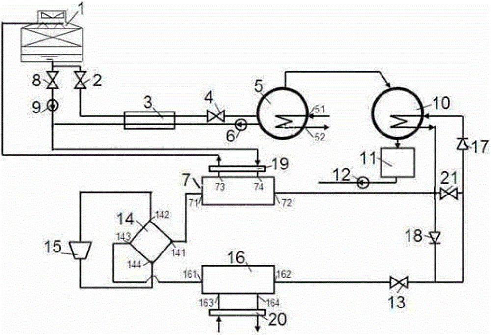
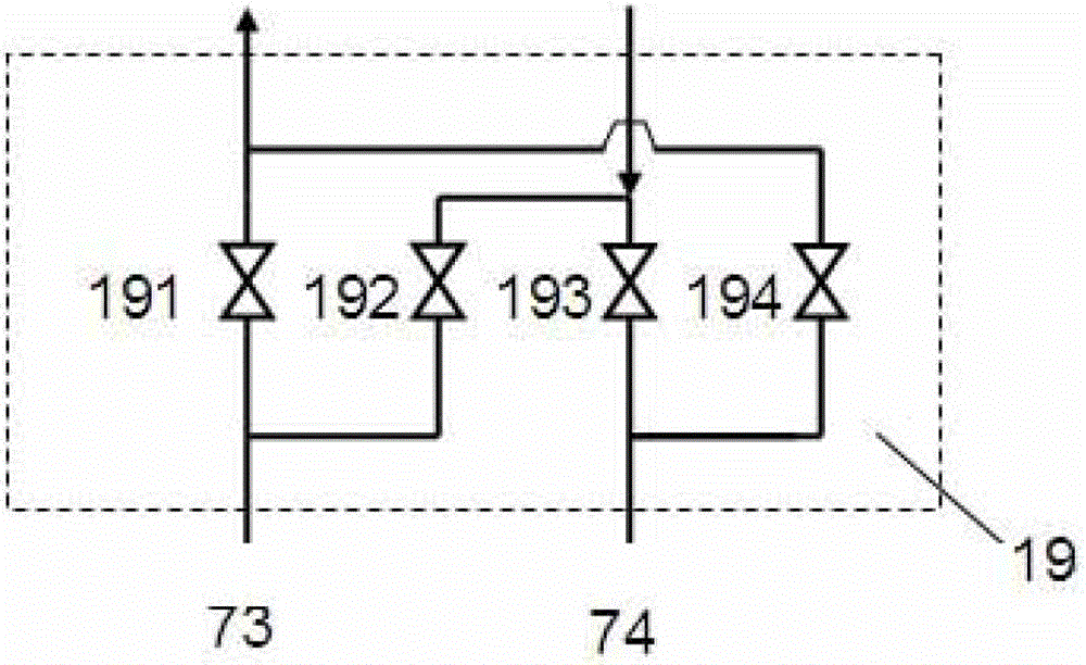
[0016] Implementation example 1, figure 1 A boiling regenerative heat source tower heat pump system is given; it includes heat pump subsystem, heat source tower subsystem and solution regeneration subsystem; solution regeneration subsystem includes regulating valve Ⅰ2, solution heat exchanger 3, throttle valve Ⅰ4, boiling regeneration 5, solution increasing pump 6, condenser 10, condensed water tank 11 and condensed water pump 12; heat pump subsystem includes outdoor heat exchanger 7, four-way reversing valve 14, compressor 15, indoor heat exchanger 16, throttle valve II13, condenser 10, one-way valve I18, one-way valve II17 and bypass valve 21; heat source tower subsystem includes heat source tower 1, regulating valve II8, circulation pump 9, outdoor heat exchanger 7 and outdoor conversion valve group 19. The three subsystems mentioned above are coupled, that is, the heat pump subsystem is coupled with the heat source tower subsystem through the outdoor heat exchanger 7 , and...


PUM


Abstract

The invention discloses a boiling regeneration type heat pump system for a heat source tower. The heat source tower is respectively connected with an adjusting valve I and an adjusting valve II; the adjusting valve I, a solution heat exchanger, a throttling valve I, a boiling type regenerator and a solution pump are sequentially connected; the solution pump is further connected with the solution heat exchanger; the adjusting valve II is connected with a cooling water pump; the cooling water pump is respectively connected with an outdoor change-over valve group and the solution heat exchanger; the boiling type regenerator is connected with an external low-level heat source; the outdoor change-over valve group is respectively connected with the solution heat exchanger, the hot source tower and the outdoor heat exchanger; the outdoor heat exchanger is connected with a four-way reversing valve; the four-way reversing valve is respectively connected with a compressor and a port of an indoor heat exchanger; the port of the indoor heat exchanger is respectively connected with a throttling valve II and an indoor reversing valve group; the throttling valve II is respectively connected with a one-way valve I and a one-way valve II; the one-way valve II is connected with a condenser; the condenser is connected with the one-way valve I and the outdoor heat exchanger; and a bypass valve is respectively connected with the one-way valve II and the condenser.

Description

technical field [0001] The invention relates to the technical field of refrigeration and air conditioning equipment, in particular to a boiling regenerative heat source tower heat pump system. Background technique [0002] Water-cooled chillers are a very common configuration in air-conditioning systems, but they cannot function in winter. In order to meet the needs of heat load, it is necessary to add a special heating system, such as equipped with a boiler room or a heat exchange station, which increases to a certain extent The initial investment of the system is reduced, and it is not energy-saving. If the air source heat pump system is used, there is no need to configure a special heating system, and the system also has a high COP in winter conditions, but it is prone to frost in winter. In recent years, some scholars have proposed a heat source tower heat pump system that uses heat source towers to absorb heat from the air in winter heating conditions, and has verified...

Claims


Application Information

Patent Timeline
Patent Type & Authority Patents(China)
IPC IPC(8): F25B13/00F25B15/06F25B41/04
CPCY02B30/62Y02A30/27
Inventor 王厉骆菁菁
Owner ZHEJIANG SCI-TECH UNIV
Why Eureka
Try Eureka