Method and device for precisely measuring ultrasonic wave transmission time

A transmission time and precise measurement technology, which is applied in the field of precision sensors and detection, can solve the problems of difficult instrument development and achieve good real-time effects

Inactive Publication Date: 2012-06-27
CHONGQING UNIV OF TECH
View PDF0 Cites 0 Cited by
  • Summary
  • Abstract
  • Description
  • Claims
  • Application Information

AI Technical Summary

Problems solved by technology

If a conventional timing and counting circuit is used, the frequency of the clock circuit must reach at least 1G, which is obviously difficult to achieve for instrument development.

Method used


Image

  • Method and device for precisely measuring ultrasonic wave transmission time
  • Method and device for precisely measuring ultrasonic wave transmission time
  • Method and device for precisely measuring ultrasonic wave transmission time

Examples


Embodiment Construction

[0030] The technical solution of the present invention will be described in further detail below in conjunction with the accompanying drawings.

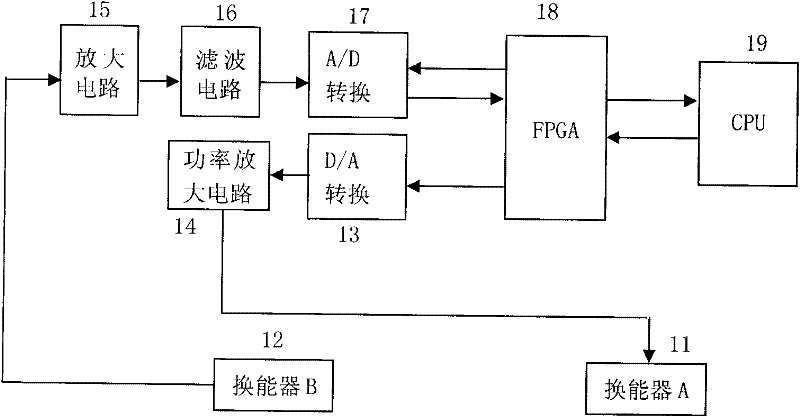
[0031] see figure 1 , the hardware circuit of this method is mainly by ultrasonic transducer A 11, transducer B 12, central processing unit CPU 19, field programmable gate array FPGA 18, A / D conversion circuit 17, filter circuit 16, amplifying circuit 15 , a power amplifier circuit 14, and a D / A conversion circuit. The ultrasonic transducer A 11 and the transducer B 12 are placed on the same straight line at a certain distance, and there is a medium capable of propagating ultrasonic waves between the two transducers, such as air, water, steel and so on. Ultrasonic transducers are piezoelectric sensors.

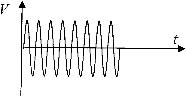
[0032] see figure 2 , is the drive signal on the ultrasonic transducer A, it is the digital sinusoidal signal generated in the FPGA converted into an analog sinusoidal signal by the D / A conversion circuit, and then amplified by t...


PUM


Abstract

The invention relates to a method and a device for precisely measuring ultrasonic wave transmission time. The method adopts two ultrasonic wave transducers A and B, a hardware circuit and a software subdivision algorithm. The hardware circuit mainly comprises an ultrasonic wave transducer drive circuit, an ultrasonic wave return signal filter circuit, an amplification circuit and a signal processing circuit. The signal processing circuit comprises an analog-to-digital (A / D) converter, an FPGA and a CPU. The CUP control the FPGA to start the ultrasonic wave transducer drive circuit to drive the transducer A to send an ultrasonic wave signal; the filter circuit filters and amplifies an ultrasonic wave return signal received by the ultrasonic wave transducer B; the A / D converter samples the wave return signal and stores the sampled data in a storage region constructed in the FPGA; and after the sampling is completed, the CPU reads the sampled data from the FPGA and accurately calculates the transmission time of the ultrasonic wave between the two transducers A and B by adopting the software subdivision algorithm. As the FPGA-based hardware circuit and the special software subdivisionalgorithm are adopted, the method and the device can realize the measurement of the ultrasonic wave transmission time with nanosecond precision and ensure good real-time.

Description

technical field [0001] The invention belongs to the technical field of precision sensors and detection, and in particular relates to a precision measurement technology of ultrasonic transmission time. Background technique [0002] The salient features of ultrasonic waves are high frequency, thus short wavelength, small diffraction phenomenon, good directionality, and directional propagation. In liquids and solids, the attenuation is small and the penetrating ability is strong. When encountering impurities or interfaces, there will be significant reflection. With the development of electronic technology, ultrasonic technology is more and more used in the precise measurement of distance and flow. [0003] When the ultrasonic wave propagates in the fluid, the time difference between the forward flow direction and the reverse flow direction is different. For example, the propagation speed of ultrasonic waves in clean water is about 1450m / s. Under the conditions of pipe diamete...

Claims


Application Information

Patent Timeline
Patent Type & Authority Patents(China)
IPC IPC(8): G01H17/00G01S7/52
Inventor 张兴红王先全陈锡侯冯济琴杨继森万文略高忠华刘小康
Owner CHONGQING UNIV OF TECH
Why Eureka
Try Eureka