Device for measuring modulation transfer function of optical system and method thereof

A modulation transfer function and optical system technology, applied in the direction of testing optical performance, etc., can solve the problems affecting the measurement accuracy of the modulation transfer function, increase the measurement error of the modulation transfer function, increase the volume and cost of the measuring instrument, and achieve a simple structure and avoid assembly. and calibration work, the effect of increasing the sampling rate

Inactive Publication Date: 2010-08-25
SUZHOU UNIV
View PDF1 Cites 33 Cited by
  • Summary
  • Abstract
  • Description
  • Claims
  • Application Information

AI Technical Summary

Problems solved by technology

[0006] The following problems exist in the use of the relay amplification system: (1) the image quality of the relay amplification system will directly affect the measurement accuracy of the modulation transfer function; to modulate the increase in the measurement error of the transfer function; (3) the high-magnification relay amplification system will weaken the energy on the detector pixel and reduce the signal-to-noise ratio; (4) the use of the relay amplification system will increase the volume of the measuring instrument and cost increase

Method used


Image

  • Device for measuring modulation transfer function of optical system and method thereof
  • Device for measuring modulation transfer function of optical system and method thereof
  • Device for measuring modulation transfer function of optical system and method thereof

Examples


Embodiment 1

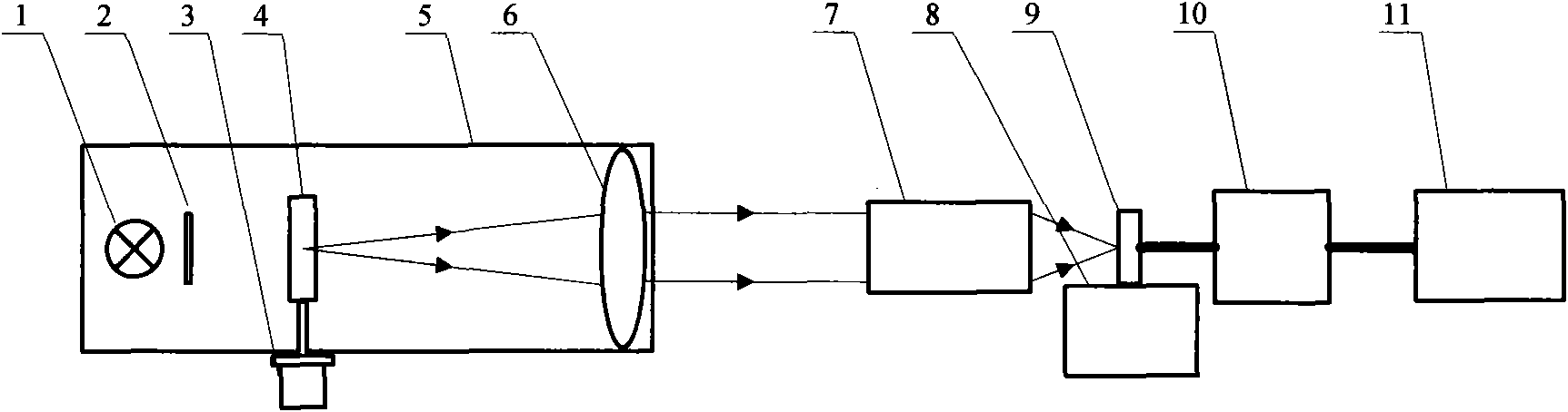
[0032] Embodiment one: referring to accompanying drawing 1, it is the structural representation of the modulation transfer function measuring device that this embodiment provides, and this device comprises target generator 5, linear motion platform 8, focal plane detector 9, detector drive and video acquisition Module 10, data processing system (computer) 11, optical system 7 of the measured modulation transfer function.

[0033] The target generator 5 is used to provide a specific knife-edge target for the modulation transfer function test, which includes a light source 1 , an optical filter 2 , a motor 3 , a knife-edge target 4 , and a collimating objective lens 6 . Among them, the knife-edge target is placed at the focal point of the collimating objective lens, and the light source is used to illuminate the target. By changing different filters, the output wavelength of the target generator can be changed. The motor can drive the target to rotate around its center, and the ...


PUM


Abstract

The invention discloses a device for measuring a modulation transfer function of an optical system and a method thereof. A target generator of the device comprises a knife edge target (4), a light source (1) and an electrical machine (3), wherein the electrical machine drives the knife edge target (4), so that an inclined angle beta is formed between the arrangement direction of a knife edge pixel (12) of the knife edge target (4) and that of a pixel (13) of an area array detector, and the inclined angle meets the following condition: ds=d sin beta, wherein the ds is a sampling distance, and the d is the size of the edge length of the pixel of the area array detector. When measuring, the modulation transfer function, the electrical machine drives the knife edge target (4) to rotate at the angle of beta to perform image data collecting and data processing so as to obtain modulation transfer function of the optical system to be measured. The invention adopts the knife edge target to realize an oversampling technology and improve the sampling rate, thereby being capable of measuring the modulation transfer function of the optical system to be measured without a relay amplifying system, being capable of measuring the maximum frequency which is higher than the Nyquist frequency of the area array detector, simplifying a measuring system, and avoiding complex assembling and correcting work when manufacturing apparatuses.

Description

technical field [0001] The invention relates to a device and method for measuring the modulation transfer function of an optical system. Background technique [0002] The modulation transfer function reflects the frequency response characteristics of an optical system or an optoelectronic system, and is an important performance index for quantitatively evaluating the imaging quality of an optical system or an optoelectronic system. [0003] The early modulation transfer function measurement adopts the scanning method, that is, the unit detector is used to scan the image plane to complete the measurement. With the maturity of area array detectors such as CCD and CMOS, the current measurement of modulation transfer function mainly adopts image Fourier analysis method, that is, pinholes, slits, etc. are used as targets, and CCD or CMOS area array detectors are used to detect the light intensity of the image plane. The distribution is followed by computer analysis processing to...

Claims


Application Information

Patent Timeline
Patent Type & Authority Applications(China)
IPC IPC(8): G01M11/02
Inventor 陈新华周建康陈宇恒季轶群沈为民
Owner SUZHOU UNIV
Why Eureka
Try Eureka