Quartz tuning fork strengthened photoacoustic spectroscopy gas sensor based on acoustic resonator

A technology of quartz tuning fork and photoacoustic spectroscopy, which is applied in the direction of color/spectral characteristic measurement, etc., can solve the problems of increasing the manufacturing cost and using cost of the device, making the acoustic resonance condition not fully satisfied, reducing the effect of resonance enhancement, etc., and reducing the manufacturing cost. And the cost of use and maintenance, the effect of improvement, and the effect of eliminating noise

Inactive Publication Date: 2010-08-25
ANHUI INST OF OPTICS & FINE MECHANICS - CHINESE ACAD OF SCI
View PDF1 Cites 48 Cited by
  • Summary
  • Abstract
  • Description
  • Claims
  • Application Information

AI Technical Summary

Problems solved by technology

However, there are deficiencies in this device. First, in order to form resonance, the optical path, that is, the laser beam must pass through two thin tubes and the tuning fork incision of the quartz tuning fork, and the width of the tuning fork incision is generally only 0.2 to 0.3mm. Therefore, the laser The beam quality of the source must be very good, that is, the focused spot must be able to pass through the tuning fork cutout of the quartz tuning fork, which not only increases the difficulty of device adjustment, but also increases the manufacturing cost and use cost of the device; secondly, it is used for resonance enhancement There is a quartz tuning fork between the two thin tubes of the signal, and there is a gap between the quartz tuning fork and the two thin tubes, so that the acoustic resonance cond

Method used


Image

  • Quartz tuning fork strengthened photoacoustic spectroscopy gas sensor based on acoustic resonator
  • Quartz tuning fork strengthened photoacoustic spectroscopy gas sensor based on acoustic resonator
  • Quartz tuning fork strengthened photoacoustic spectroscopy gas sensor based on acoustic resonator

Examples


Embodiment Construction

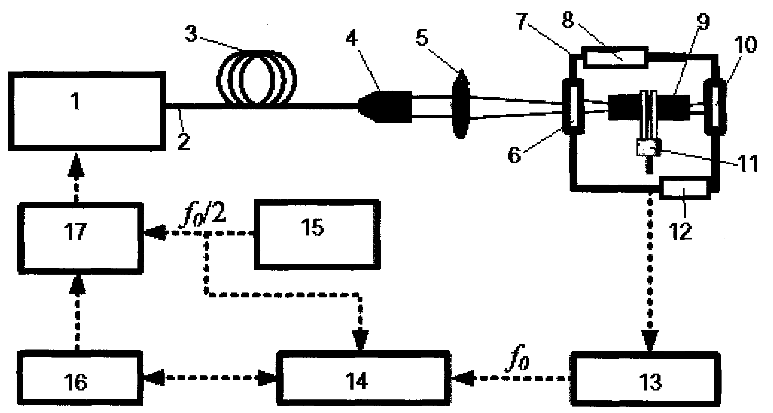
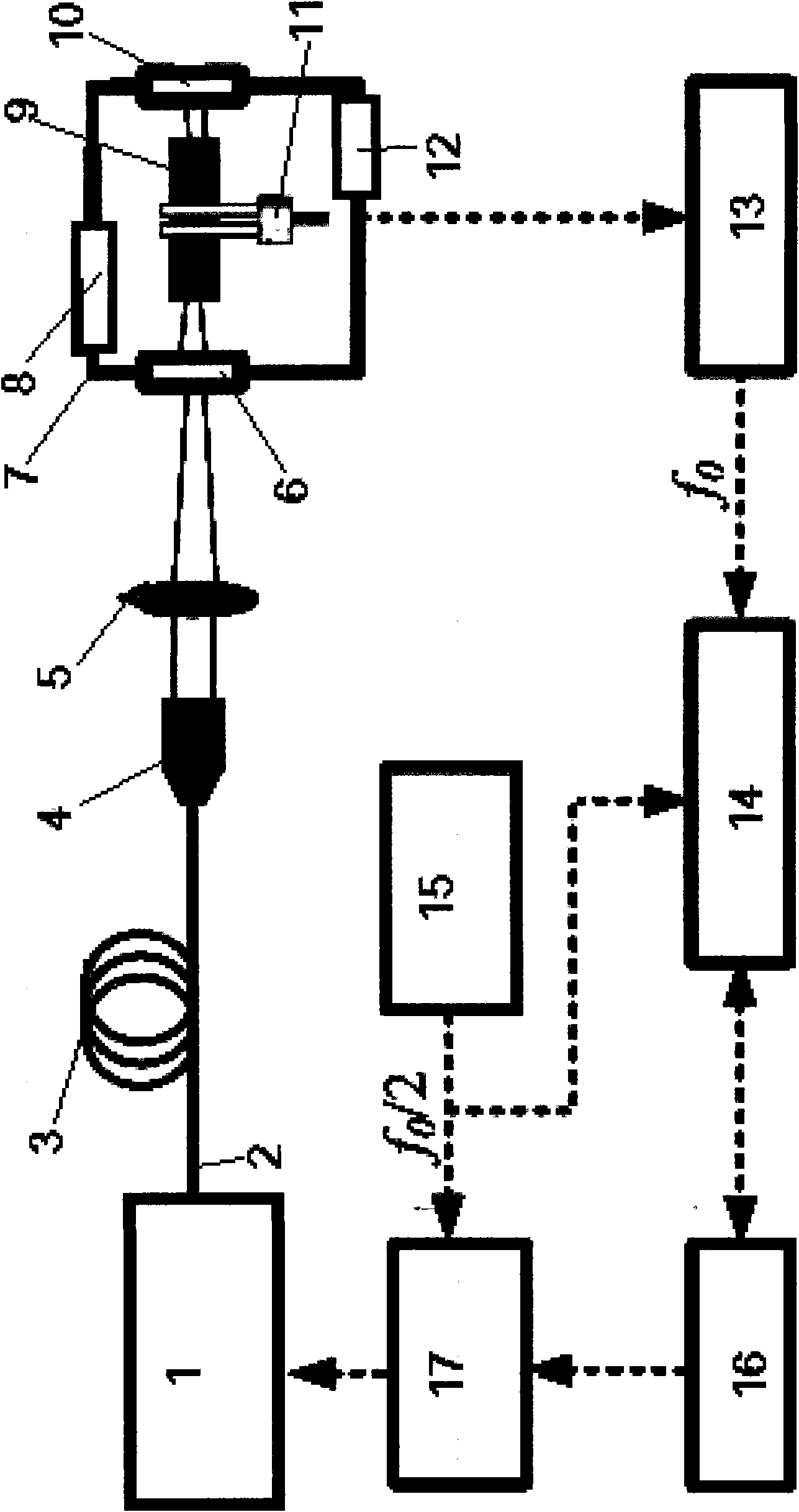
[0016] Referring to Figure 1, Figure 2, Figure 3 and Figure 4, the optical path 2 of the laser 1 is provided with an optical fiber 3, a collimating lens 4, a focusing lens 5 and an incident window 6 of a sample cell 7, as well as an acoustic resonator 9 and a sample cell. 7 of the exit window 10. among them,

[0017] The upper and lower sides of the sample cell 7 are respectively provided with an air inlet 8 and an air outlet 12.

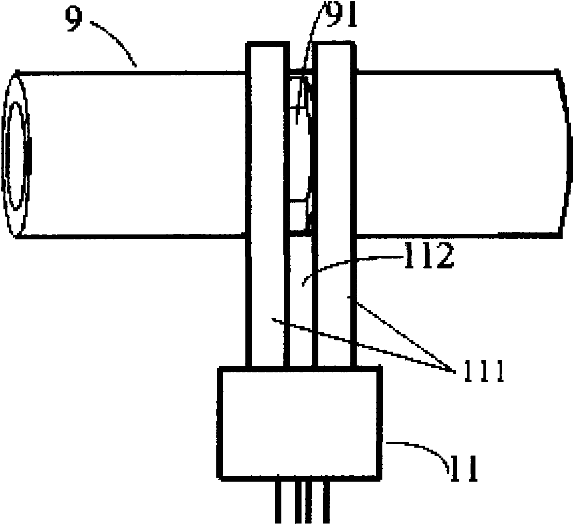
[0018] The acoustic resonant cavity 9 is a tube with a length of 8 mm, an outer diameter of 0.7 mm, and an inner diameter of 0.45 mm, and a slit 91 with a width of 0.15 mm and a length of 0.45 mm is placed in the middle. The slit 91 is perpendicular to the tube length of the acoustic cavity 9, the tube axis of the acoustic cavity 9 is coaxial with the optical path 2, and the focus of the focusing lens 5 is located at the slit 91 in the acoustic cavity 9.

[0019] The slit 91 handles the tuning fork arm 111 of the quartz tuning fork 11, and the distance b...


PUM

PropertyMeasurementUnit
Lengthaaaaaaaaaa
Outer diameteraaaaaaaaaa
Inner diameteraaaaaaaaaa

Abstract

The invention discloses a quartz tuning fork strengthened photoacoustic spectroscopy gas sensor based on an acoustic resonator. The gas sensor comprises a laser (1), a focusing lens (5), a tubular resonator, a quartz tuning fork (11), a function generator (15) electrically connected with the laser (1) and a lock-in amplifier (14) electrically connected with the quartz tuning fork (11), wherein the focusing lens (5) and the tubular resonator are arranged on an optical path (2) of the laser (1); the function generator (15) is electrically connected with the lock-in amplifier (14); the tubular resonator is the acoustic resonator (9) with a slit (91) in the middle; the length of the acoustic resonator is not more than 10mm, the external diameter is not more than 1mm and the internal diameter is not more than 0.6mm; the width of the slit (91) is not more than 0.2mm and the length is not more than the internal diameter of the acoustic resonator (9); prongs (111) of the quartz tuning fork (11) are positioned on the slit (91) and the distances between the prongs (111) and the slit (91) are not less than 0.001mm. The gas sensor has simple structure, small volume and strong anti-jamming property, works stably, is convenient to adjust and use and can be extensively used for detecting the components or contents of the gases.

Description

Technical field [0001] The invention relates to a gas sensing device, in particular to a quartz tuning fork enhanced photoacoustic spectrum gas sensing device based on an acoustic resonance cavity. Background technique [0002] With the continuous development of economy and society, environmental problems have become increasingly prominent. In order to effectively monitor and predict environmental pollution, people have made unremitting efforts, trying to detect the composition or content of substances through photoacoustic spectroscopy technology. For example, in the US patent specification US2005 / 0117155A1 published on June 2, 2005 A "quartz enhanced photoacoustic spectroscopy device" mentioned. It intends to provide a photoacoustic spectroscopy device using a quartz tuning fork to detect the composition or content of gaseous substances. It is composed of the laser and the focusing lens, tubular resonator and quartz tuning fork placed on the optical path, and the input end of...

Claims


Application Information

Patent Timeline
IPC IPC(8): G01N21/39
Inventor 高晓明刘锟张为俊谈图
Owner ANHUI INST OF OPTICS & FINE MECHANICS - CHINESE ACAD OF SCI
Why Eureka
Try Eureka