Multi-junction solar cell with high peak current density tunnel junction

A multi-junction solar cell and current density technology, which is applied in circuits, photovoltaic power generation, electrical components, etc., can solve the problems of uneven doping concentration, high cost, and limited application of multi-junction III-V material compound solar cells, etc. Achieve the effect of steep interface and high doping concentration

Active Publication Date: 2010-08-25
XIAMEN SANAN OPTOELECTRONICS TECH CO LTD
View PDF2 Cites 10 Cited by
  • Summary
  • Abstract
  • Description
  • Claims
  • Application Information

AI Technical Summary

Problems solved by technology

[0003] Under concentrating conditions, multi-junction III-V material compound solar cells in existing photovoltaic systems have achieved a photoelectric conversion efficiency of more than 40%, and will be further improved in the near future, which is the only photoelectric conversion efficiency of 40%. devices; compared with Si or other thin-film cells, the high cost limits the application of multi-junction III-V material compound solar cells; the current solution to this cost-efficiency dilemma lies in the use of high-power concentrating systems, through cheaper Therefore, multi-junction solar cells are required to be able to work at as high a concentrating solar multiple as possible. Therefore, the tunneling junction peak current of high-concentrating solar cells is required to be as high as possible (for example, at 2000 times concentrating Under the sun conditions, the working current of the battery is close to 30A / cm 2 ), the peak current density of the tunnel junction of the battery must be much greater than 30A / cm 2
[0004] At present, the tunnel junctions commonly used in GaInP / GaInAs / Ge multi-junction solar cells are n-GaAs / p-GaAs and n-GaInP / p-AlGaAs, where the n-type dopant uses Si or Te, and uses Si doping, The doping concentration usually does not exceed 8×10 18 cm -3 , using Te doping, although a higher doping concentration can be obtained, but due to the hysteresis effect of Te in the doping process, the doping concentration is not uniform, and it is difficult to obtain a high peak current at the tunnel junction; n-GaInP / p- AlGaAs tunneling junctions are also difficult to obtain high peak current tunneling junctions due to their large band gaps.

Method used


Image

  • Multi-junction solar cell with high peak current density tunnel junction
  • Multi-junction solar cell with high peak current density tunnel junction

Examples


Embodiment Construction

[0029] The present invention will be further described below in conjunction with the accompanying drawings and embodiments.

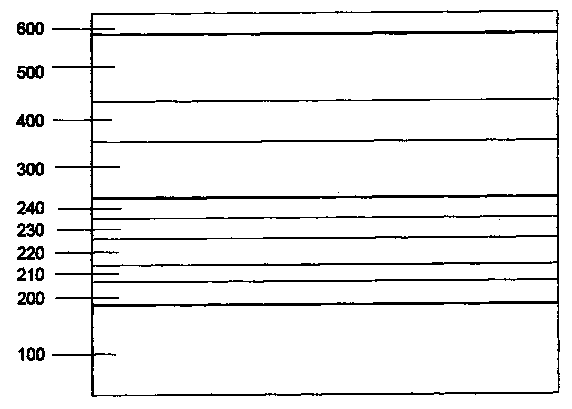
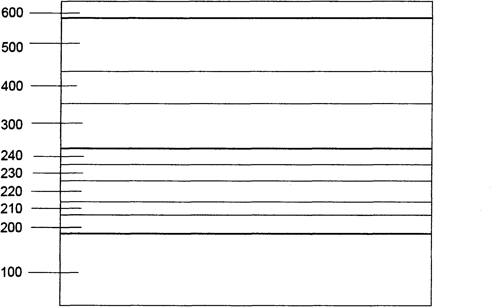
[0030] As shown in Figure 1, a multi-junction solar cell with a high peak current density tunnel junction, the tunnel junction connecting the Ge bottom cell 100, the GaInAs middle cell 300 and the GaInP top cell 500 has five layers, and the first layer is anti-diffusion The first layer is an n-type GaInP film 200; the second layer is a GaAs film 210 co-doped with Si and Te; the third layer is a Te-doped GaAs film 220; the fourth layer is a C-doped AlGaAs film 230; the fifth layer is an anti- The diffusion layer is a p-type AlGaInP thin film 240 .

[0031] The above-mentioned multi-junction solar cell with high peak current density tunneling junction, its preparation steps are as follows:

[0032] In the MOCVD system, the first Ge bottom cell 100 is grown.

[0033] Grow a layer of n-type anti-diffusion layer GaInP film 200, the growth temperature is 65...


PUM


Abstract

The invention discloses a multi-junction solar cell with a high peak current density tunnel junction, in particular a high-concentration GaInP / GaInAs / Ge three-junction solar cell, which is characterized in that: a tunnel junction connecting a Ge bottom cell, a GaInAs intermediate cell and a GaInP top cell have five layers, wherein the first layer is an n-type (AlxGa1-x)InP or AlGaAs nonproliferation layer; the second layer is Si and Te codoped GaAs membrane; the third layer is Te doped GaAs membrane; the fourth layer is a C doped AlGaAs membrane; and the fifth layer is a p-type (AlxGa1-x)InP or AlGaAs nonproliferation layer. The solar cell can obtain the peak current density of the tunnel junction of more than 150A / cm<2>. The multi-junction solar cell with the tunnel junction can work under a condition of 2,000-times solar concentration.

Description

technical field [0001] The invention relates to a multi-junction solar cell, in particular to a multi-junction solar cell with high peak current density tunneling junction. Background technique [0002] As we all know, a solar cell is an optoelectronic device that converts light energy into electrical energy. In a multi-junction series solar cell, since each sub-cell is composed of p-n junctions, if they are directly connected in series, the p-n junctions are reverse-biased and non-conductive. The tunnel junction structure can solve this problem; the peak current of the tunnel junction increases with the increase of the doping concentration and decreases with the increase of the band gap; in order to obtain a high-efficiency solar cell, a high conductivity must be used , High tunneling current tunneling junction, so it is necessary to use low bandgap material tunneling junction, increase the doping concentration of the tunneling junction, solve a series of process problems c...

Claims


Application Information

Patent Timeline
Patent Type & Authority Applications(China)
IPC IPC(8): H01L31/052H01L31/0352H01L31/18H01L31/054
CPCY02E10/52Y02P70/50
Inventor 林桂江王良均丁杰吴志强
Owner XIAMEN SANAN OPTOELECTRONICS TECH CO LTD
Why Eureka
Try Eureka