

Intermediate frequency power circuit
An intermediate frequency power supply and circuit technology, which is applied to electrical components, crucible furnaces, furnace types, etc., can solve the problems of poor heat preservation effect, short effective working time of furnace body, thin furnace wall, etc., so as to reduce production cost and improve effective working time. Effect
Inactive Publication Date: 2010-08-25
QINGDAO UNIV
View PDF0 Cites 7 Cited by
- Summary
- Abstract
- Description
- Claims
- Application Information
AI Technical Summary
Problems solved by technology
The purpose of the present invention is to at least solve one of the above-mentioned technical defects, especially solve the technical defect of the low Q value of the intermediate frequency power supply circuit in the prior art, thereby solving the problem of the intermediate frequency induction heating furnace caused by the limitation of the Q value of the intermediate frequency power supply circuit The furnace wall is thin, the insulation effect is poor, the furnace life is short, the safety is poor, the effective working time of the furnace body is short, etc.
Method used
View moreImage
Smart ImageViewing Examples

Examples
Embodiment Construction
Login to View More PUM
 Abstract
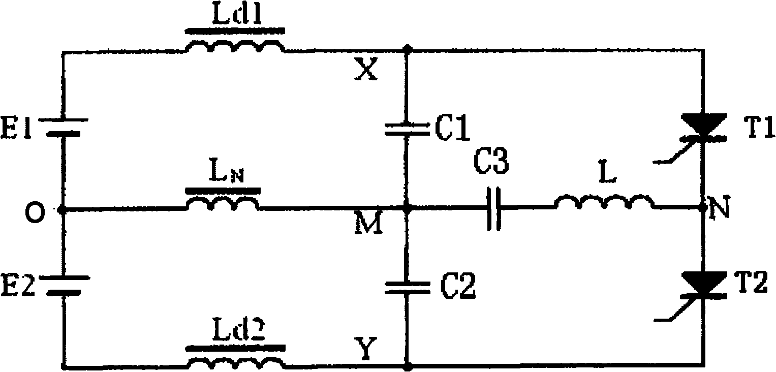
The invention provides an intermediate frequency power circuit, which comprises a first voltage source, a second voltage source, a first smoothing reactor, a second smoothing reactor, a first resonant capacitor, a second resonant capacitor, a first power device, a second power device, and a furnace induction coil, wherein the first voltage source is connected in series with the second voltage source; the first smoothing reactor and the second smoothing reactor are connected with the first voltage source and the second voltage source respectively; the first resonant capacitor and the second resonant capacitor are connected with the first smoothing reactor and the second smoothing reactor respectively, and are mutually connected in series; the first power device is connected with the first smoothing reactor and the first resonant capacitor, and the second power device is connected with the second smoothing reactor and the second resonant capacitor; and the furnace induction coil is connected between a second node and a fifth node. The intermediate frequency power circuit has the characteristics of higher Q value of a resonator system, and higher power output so as to thicken the furnace wall, greatly improve effective work time of the furnace and reduce production cost. The intermediate frequency power circuit has great significance in the fields of metal melting, induction heating and the like.
Description
technical field The invention relates to the technical field of power circuits, in particular to an intermediate frequency power circuit. Background technique Induction heating furnaces are widely used in metallurgy, smelting and other fields. Compared with traditional arc heating methods, induction heating furnaces are heated by induction, so they have energy saving, low pollution, low gas content in molten steel, less burning loss of alloy elements, electromagnetic stirring and can Accurate temperature control and other advantages. The intermediate frequency power supply for induction heating is a resonant system, and its Q value can be defined as: system reactive power P s and its output real power P R The ratio of Q=P s / P R . When the induction coil passes an alternating current i with an angular frequency ω, the magnetic flux generated by the coil is divided into Φ 1 , Φa, and Φ 2 Three parts, among them, Φ 1 is the magnetic flux passing through the induction c...
Claims
Login to View More Application Information
Patent Timeline
 IPC IPC(8): H02M7/44H02M7/515F27B14/06
Inventor罗马傅强杨艳
OwnerQINGDAO UNIV