Method for testing lightwave transmission characteristics in atmospheric channel

A technology of transmission characteristics and test methods, applied in the fields of optical radar, optics, and wireless optical communication, can solve the problems that the performance of the wireless optical communication system is in its infancy and has not yet been consulted, and achieves the effect of reducing the number of testers and low power consumption

Inactive Publication Date: 2012-09-12
UNIV OF ELECTRONICS SCI & TECH OF CHINA
View PDF4 Cites 0 Cited by
  • Summary
  • Abstract
  • Description
  • Claims
  • Application Information

AI Technical Summary

Problems solved by technology

[0006] At this stage, the measurement of atmospheric optical parameters has a good research foundation, but the research on the influence of atmospheric effects on the performance of wireless optical communication systems is still in its infancy
Moreover, the "light wave transmission characteristic testing method or device" at home and abroad is only a method or device for testing the visibility in the light wave transmission characteristic alone; ups and downs) or one of the two turbulence effects combined for testing methods or devices; no reference has been found at home and abroad that the present invention uses a complete set of test methods and devices to complete all turbulence effects (arrival angle fluctuations, drift, expansion, scintillation) And the method or device of attenuation effect test

Method used


Image

  • Method for testing lightwave transmission characteristics in atmospheric channel
  • Method for testing lightwave transmission characteristics in atmospheric channel
  • Method for testing lightwave transmission characteristics in atmospheric channel

Examples


Embodiment Construction

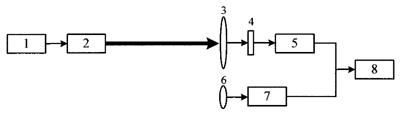
[0029] In the aforementioned technical solution, the light wave transmission characteristic test system built in step 1 is composed of a laser emitting sub-unit, a laser receiving sub-unit and a data processing sub-unit.

[0030] The laser light source 1 of the transmitting extension adopts a precise laser light source with a 800nm ​​band, a maximum output power of 75mW, and a power stability better than 1%; The wavelength is 800nm, the beam divergence angle is better than 150urad, and the beam diameter is less than 150mm.

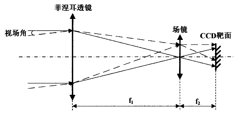
[0031] In the receiving extension, the receiving aperture of the Fresnel lens 3 of the Fresnel screen receiving optical path is less than 500mm, and the half-angle of the receiving field of view is less than 0.50; the frame rate of No. 1 digital camera 5 is less than 100fps. The specific optical path is as figure 2 As shown, it is made up of Fresnel lens 3, field lens 4 and No. 1 digital camera 5. Wherein, the focal length of Fresnel lens 3 is f1, and t...


PUM


Abstract

The invention relates to a method for testing lightwave transmission characteristics in an atmospheric channel, which belongs to the technical field of optics and is used in fields such as wireless optical communication, optical radar and the like. A testing system which comprises a laser emission subsystem, a receiving subsystem and a data processing subsystem is set up, wherein the receiving subsystem comprises two independent receiving light paths: one is a Fresnel screen receiving light path which consists of a Fresnel lens, a field lens and a No. I digital camera and is used for testing attenuation, drift and extension; and the other is an arrival angle fluctuation receiving light path which consists of a receiving lens and a No. II digital camera and is used for testing arrival angle fluctuation. The invention only adopts one set of testing system to carry out the testing of four types of turbulence effects and an attenuation effect, thus having great significance in reducing the number of hardwares needed by the testing of the atmospheric turbulence effects and the attenuation effect, reducing the number of testers, expenditure and period, realizing the miniaturization, light weight and low power consumption of the testing system and implementing quick, convenient and overall lightwave transmission characteristic tests.

Description

technical field [0001] The invention belongs to the field of optical technology, and is mainly used for testing the drift, expansion, scintillation, angle of arrival fluctuation turbulence effect characteristics and optical power attenuation characteristics of laser light waves in the near-earth atmospheric turbulent channel, and can be used in wireless optical communication, optical radar and other fields. Background technique [0002] Wireless optical communication has the characteristics of high transmission bit rate, confidentiality, anti-interference, etc., and plays a very important role in military and national defense fields and civilian fields. Due to the interaction between atmospheric molecules and particles in the atmospheric channel and the transmitted light waves, there are turbulence effects such as arrival angle fluctuation, drift, expansion, and light intensity fluctuations in the transmission of laser light waves in the near-Earth atmospheric turbulent chann...

Claims


Application Information

Patent Timeline
Patent Type & Authority Patents(China)
IPC IPC(8): H04B10/08H04B10/07
Inventor 李晓峰蒋大钢邓科胡玮
Owner UNIV OF ELECTRONICS SCI & TECH OF CHINA
Why Eureka
Try Eureka