Laser processing method and device for non-through hole

A laser processing method and non-through hole technology, which are used in laser welding equipment, metal processing equipment, manufacturing tools, etc.

Inactive Publication Date: 2010-09-01
王晓东
View PDF6 Cites 14 Cited by
  • Summary
  • Abstract
  • Description
  • Claims
  • Application Information

AI Technical Summary

Problems solved by technology

However, most of the previous technical methods can only monitor the formation of through holes. For example, patent

Method used


Image

  • Laser processing method and device for non-through hole
  • Laser processing method and device for non-through hole
  • Laser processing method and device for non-through hole

Examples


Embodiment Construction

[0023] In order to further clarify the method and device adopted by the present invention to achieve the intended invention purpose, the laser drilling method and device proposed by the present invention and its specific implementation methods, steps and features will be described in detail below in conjunction with the accompanying drawings and preferred embodiments.

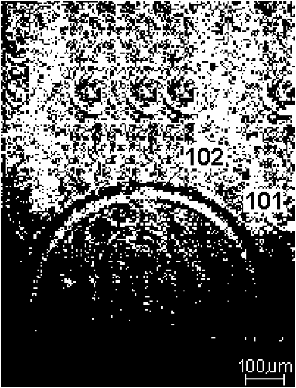
[0024] High-intensity laser pulses are irradiated on the surface of the material, when the power density is greater than about 2×10 8 W / cm 2 When the surface layer of the material is explosively vaporized, the laser-supported detonation wave (LSDW) phenomenon occurs. The high-temperature and high-pressure material gas plasma and air plasma rapidly expand outward from the laser action area to form laser shock waves 101, such as figure 1 As shown, the hemispherical laser shock wave front 102 expands toward the outside atmosphere with the laser action point as the center. The high temperature, high pressure, and...


PUM


Abstract

The invention discloses a laser processing method and a laser processing device for a non-through hole. The method comprises the following steps of: focusing a pulse laser beam 4 emitted by a pulse laser device 401 on a to-be-perforated position of a workpiece 404 through a perforating optical system 403 to implement perforating; and when the pulse laser device 401 emits laser pulse, trigging a synchronous time delay module 405, trigging a shock wave photographing system 406 after certain time delay, photographing shock wave 407 produced by the interaction of the laser pulse and the workpiece 404, inputting photo data into a control computer 409 through an image acquisition module 408, analyzing and processing a shock wave photo by the control computer 409, obtaining the real-time depth of a processed hole by consulting processing reference data stored in the control computer 409, and judging whether the hole depth meets the requirement so as to control the pulse laser device 401 to continue or terminate perforating. The method and the device perform closed-loop control on the perforated hole depth during laser perforating so as to greatly improve the laser processing precision and efficiency of the non-through hole.

Description

technical field [0001] The present invention relates to a pulse laser processing method, in particular to a laser processing method for non-through holes. Background technique [0002] Material drilling technology has a wide range of applications in the field of industrial manufacturing. For the processed holes, according to whether they penetrate the workpiece to be punched, they can be divided into two types: through holes (also known as through holes) and non-through holes (also known as blind holes). For blind holes that require processing to a certain depth, the traditional mechanical drilling method can easily set the drilling depth to obtain blind holes with a fixed hole depth, but usually only achieve a hole diameter as small as about 100 microns, and the hole depth / aperture ratio Less than 10:1 material drilling. [0003] When the hole diameter is required to be less than 100 microns or the hole depth / aperture ratio is greater than 10:1, electron beam and laser dr...

Claims


Application Information

Patent Timeline
IPC IPC(8): B23K26/38G05B19/19B23K26/386
Inventor 王晓东
Owner 王晓东
Why Eureka
Try Eureka