
Continuous monitoring device and method of gaseous elemental mercury concentration

A monitoring device and a technology for elemental mercury, which are applied in measurement devices, color/spectral property measurement, material analysis by optical means, etc., can solve the problems of high cost, low sensitivity and complex system, and achieve low cost and simple composition. Effect

Inactive Publication Date: 2010-09-01
HARBIN INST OF TECH
View PDF1 Cites 20 Cited by
  • Summary
  • Abstract
  • Description
  • Claims
  • Application Information

AI Technical Summary

Problems solved by technology

[0004] The present invention aims to solve the problems of low sensitivity, complex system and high cost of existing gaseous elemental mercury monitoring technology, thereby providing a continuous monitoring device and method for gaseous elemental mercury concentration

Method used


Image

  • Continuous monitoring device and method of gaseous elemental mercury concentration
  • Continuous monitoring device and method of gaseous elemental mercury concentration
  • Continuous monitoring device and method of gaseous elemental mercury concentration

Examples


specific Embodiment approach 1

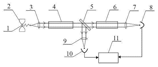
[0014] Specific implementation mode one, combine figure 1 Describe this embodiment, the continuous monitoring device of gaseous elemental mercury concentration, it is made of mercury element lamp 1, magnet 2, collimator lens 3, sample cell 4, beam splitter 5, reference cell 6, first convex lens 7, first detector 8. Composed of a second convex lens 9, a second detector 10, and a data acquisition analyzer 11, the mercury element lamp 1 is placed in the magnetic field of the magnet 2, and is arranged at the focal point of the collimating lens 3. The detection of the first detector 8 The surface coincides with the focal plane of the first convex lens 7, the detection surface of the second detector 10 coincides with the focal plane of the second convex lens 9, the output light of the mercury element lamp 1 is incident on the collimator lens 3, and is transmitted through the collimator lens 3 to obtain Parallel light, the parallel light enters the beam splitter 5 after passing thr...

specific Embodiment approach 2

[0018] Specific implementation mode two, combine figure 1 This embodiment is described. The difference between this embodiment and the first embodiment is that the beam splitter 5 is a semi-reflective and semi-transmissive beam splitter.

specific Embodiment approach 3

[0019] Specific implementation mode three, combine figure 1 Describe this embodiment, the difference between this embodiment and specific embodiment 1 is that the saturation concentration per meter of elemental mercury gas in the reference pool 6 is 0.2 ~ 20mg / m 3 .


PUM


Abstract

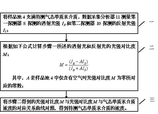
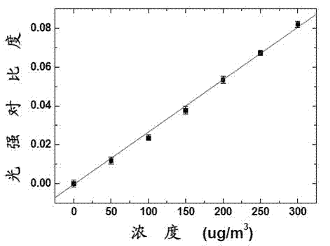
The invention provides a continuous monitoring device and a method of gaseous elemental mercury concentration, relating to the gas concentration measurement field and solving the problems of low sensitivity, complex system and overhigh cost of the existing gaseous elemental mercury monitoring technology. To the monitoring device in the invention, a mercury element lamp is arranged in a magnetic field of a magnet, the output light is subjected to transmission to obtain parallel light via a collimation lens, the parallel light enters into a spectroscope via a sample pool, the transmission light enters into a first convex lens via a reference pool and is focused on a first detector, the reflecting light enters into a second convex lens and is focused on a second detector, and the first detector and the second detector are connected with a data collection analyzer. The method is implemented as follows: 1) determining a constant A corresponding to the light intensity contrast ratio M when being zero; 2) drawing a correspondence curve of the light intensity contrast ratio M and gaseous elemental mercury medium concentration; and 3) measuring the light intensity contrast ratio M of the gaseous elemental mercury medium to be measured, and comparing with the correspondence curve to obtain the concentration of the gaseous elemental mercury medium. The invention is used for monitoring the gaseous mercury concentration.

Description

technical field [0001] The invention relates to the field of gas concentration measurement, in particular to a device and method for continuously monitoring the concentration of gaseous elemental mercury. Background technique [0002] Mercury in combustion flue gas exists in three forms: gaseous elemental mercury, gaseous divalent oxidized mercury and particulate mercury. Among them, gaseous mercury is the main form. The total mercury content is measured by thermocatalytic or chemical conversion of other forms of mercury into gaseous elemental mercury. Among the currently applied continuous monitoring systems for mercury emissions, the most commonly used gaseous elemental mercury measurement techniques are cold vapor atomic absorption spectroscopy (CVAAS) and cold vapor atomic fluorescence spectroscopy (CVAFS) techniques based on the principle of spectroscopic detection. The former can directly measure the concentration of gaseous elemental mercury in the flue gas without ...

Claims


Application Information

Patent Timeline
IPC IPC(8): G01N21/33G01N21/01
Inventor 娄秀涛王鹏王华山张云刚陈斌瑞小川张治国
Owner HARBIN INST OF TECH
Learn More