Method for manufacturing composite film gas sensor

A gas sensor and composite film technology, which is applied in the field of composite film gas sensor production, can solve the problems of potential safety hazards, inability to detect trace gases, and high power consumption, and achieve good gas sensor performance and broad market application prospects. Effect

Inactive Publication Date: 2010-09-08
FUZHOU UNIV
View PDF4 Cites 14 Cited by
  • Summary
  • Abstract
  • Description
  • Claims
  • Application Information

AI Technical Summary

Problems solved by technology

The existing commercial gas sensors are far from mature. The main problem is that it is difficult to concentrate all the advantages of the sensor in one sensor. Most sensors only have outstanding performance in a certain aspect, but the overall performance is not good.
The existing gas sensor research mainly has the following shortcomings: the power consumption is too large, the higher working temperature (200-600°C) is often used, and only higher gas concentration (ppm level) can be detected. The selectivity is not high, and the response recovery time of the multi-walled carbon nanotube (MWCNT) doped gas sensor is too long, etc.
The high operating temperature and power consumption of the gas sensor are not conducive to the application of portable products, and there are also potential safety hazards; the detection sensitivity of the target gas is not high, resulting in the inability to detect 1×10 -6 Trace gases below the concentration (ppb level); in actual use, there is still a serious cross-sensitivity phenomenon of the gas sensor to the target gas and the interfering gas, that is, the selectivity of the gas sensor is not ideal

Method used


Image

  • Method for manufacturing composite film gas sensor
  • Method for manufacturing composite film gas sensor
  • Method for manufacturing composite film gas sensor

Examples


Embodiment Construction

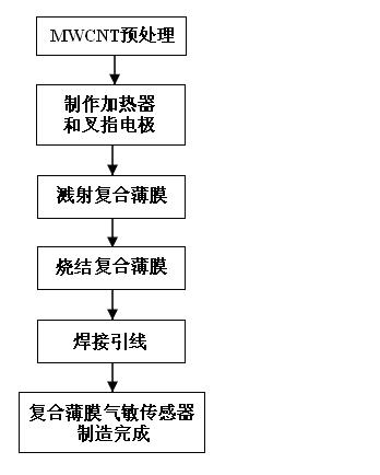
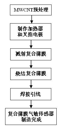
[0020] A kind of manufacture method one of composite film gas sensor of the present invention comprises the following steps:

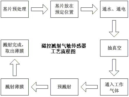
[0021] (1) Clean the substrate. The cleaning of the substrate is very important. It is necessary to remove the dust, grease and impurities on the surface of the substrate, otherwise it will affect the quality of the sputtered film.

[0022] (2) Acid treatment of MWCNT, acid treatment can effectively remove amorphous carbon impurities in carbon nanotubes, improve the dispersion of carbon nanotubes, then add and disperse MWCNTs in organic solvents, and process them in an ultrasonic oscillator After a period of 2 hours, a well-mixed suspension was obtained, which was then spin-coated respectively on the tin target and the tungsten target of the radio frequency reactive magnetron sputtering equipment;

[0023] (3) Thermally oxidize a layer of SiO on a clean silicon wafer 2 , thickness 500nm;

[0024] (4) Manufacture Al by magnetron sputtering 2 o 3 -T...


PUM

PropertyMeasurementUnit
diameteraaaaaaaaaa

Abstract

The invention relates to the technical field of manufacturing gas sensors, in particular to a method for manufacturing a composite film gas sensor. The method is characterized by comprising the following steps of: 1, performing acid treatment on MWCNT, then adding and dispersing the MWCNT into an organic solvent, treating the mixture to obtain a fully-mixed suspension, and spin-coating the suspension to a tin target and a tungsten target of a radio frequency reaction magnetron sputtering device respectively; 2, manufacturing a heater and an interdigital electrode of the sensor on a silicon chip or a ceramic tube; 3, using a radio frequency reaction magnetron sputtering technique to sputter a layer of SnO2-MWCNT film on the area of the interdigital electrode, and sputter a layer of WO3-MWCNT film on the SnO2-MWCNT film to form a composite film; 4, sintering the silicon chip or the ceramic tube attached with the film in a high-temperature furnace; and 5, welding a platinum wire between the heater of the silicon chip or the ceramic tube and an outer leading wire post of the sensor and welding a platinum wire between the electrode of the silicon chip or the ceramic tube and the outer leading wire post of the sensor respectively. The SnO2-WO3-MWCNT composite film gas sensor manufactured by the method has a high gas-sensing property and a good using effect.

Description

technical field [0001] The invention relates to the technical field of gas sensor manufacturing, in particular to a method for manufacturing a composite film gas sensor. Background technique [0002] With the advancement of science and technology, human beings have put forward higher requirements for the detection of toxic and harmful gases in the environment, and correspondingly higher standards for gas sensors. The existing commercial gas sensors are still far from mature. The main problem is that it is difficult to concentrate all the advantages of the sensor in one sensor. Most sensors only have outstanding performance in a certain aspect, but the overall performance is not good. The existing gas sensor research mainly has the following shortcomings: the power consumption is too large, the higher working temperature (200-600°C) is often used, and only higher gas concentration (ppm level) can be detected. The selectivity is not high, and the response recovery time of the...

Claims


Application Information

Patent Timeline
Patent Type & Authority Applications(China)
IPC IPC(8): C23C14/35C23C14/02G01N27/00
Inventor 林伟黄世震黄兆新陈伟
Owner FUZHOU UNIV
Why Eureka
Try Eureka