Production of fine-grained particles

A particle and particle technology, applied in the field of particle manufacturing, can solve problems such as long reaction time and difficulty in obtaining crystallinity

Inactive Publication Date: 2004-02-18
VERY SMALL PARTICLE CO LTD
View PDF4 Cites 21 Cited by
  • Summary
  • Abstract
  • Description
  • Claims
  • Application Information

AI Technical Summary

Problems solved by technology
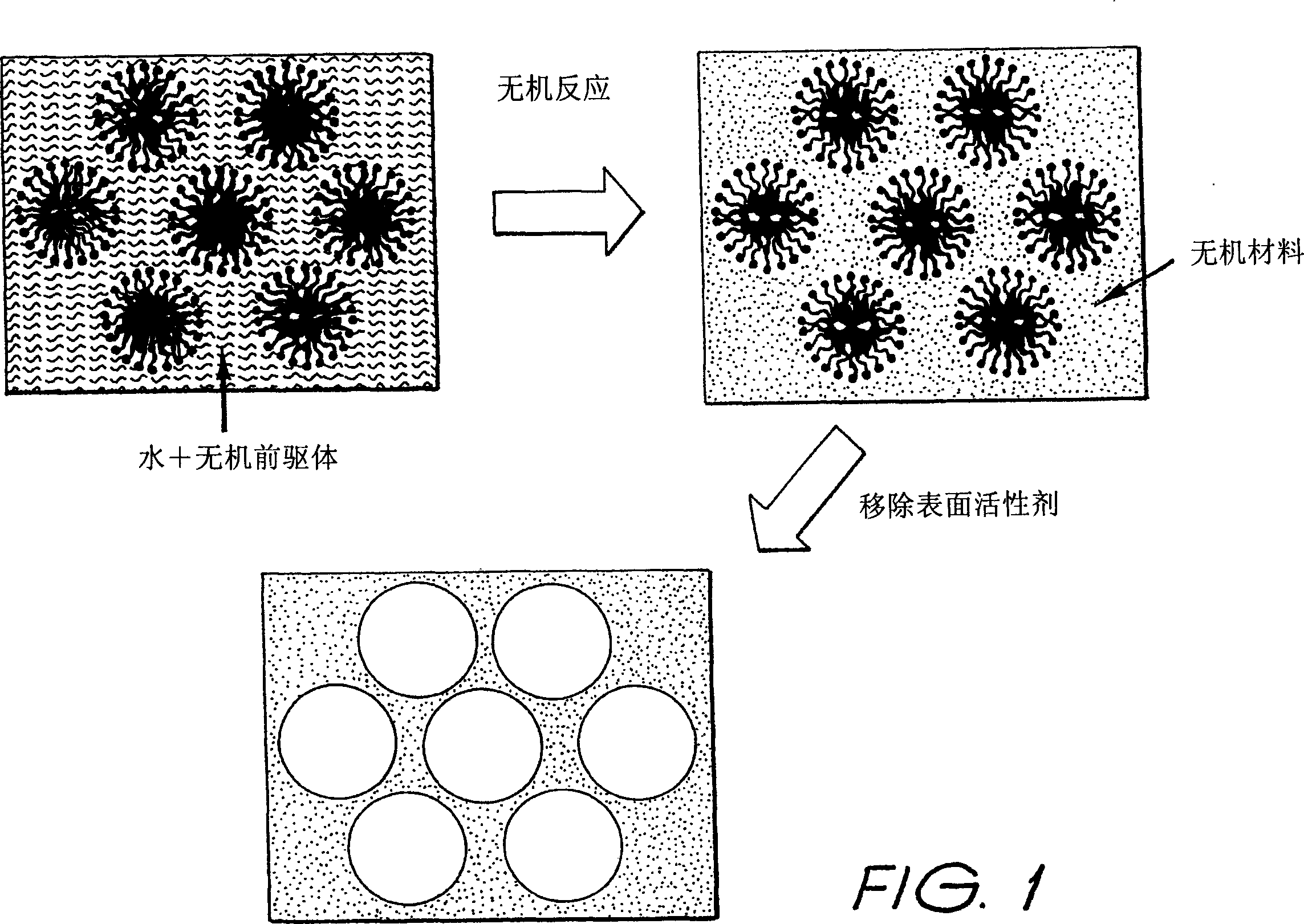
Most of the surfactant-templated processes described in the literature result in the formation of inorganic particles with particle sizes in excess of one micron
Difficult to obtain crystallinity
Lengthy reaction time due to the significant time required to form the surfactant inorganic structure in solution

Method used


Image

  • Production of fine-grained particles
  • Production of fine-grained particles
  • Production of fine-grained particles

Examples


Embodiment 1

[0124] Example 1-CeO 2 the manufacture of

[0125] Manufacturing CeO 2 to introduce the method of the present invention. Use the following steps:

[0126] Step 1: Prepare a cerium nitrate solution containing 2.5 moles / liter of cerium nitrate.

[0127] Step 2: Heat 16 grams of Brij56 surfactant and 20 mL of cerium nitrate solution to -80°C. Surfactants are liquid at this temperature. The solution was slowly stirred and added to the surfactant liquid to produce a micellar liquid.

[0128] Step 3: Cool the micellar liquid to room temperature. The solution turned into a clear gel during cooling.

[0129] Step 4: The gel is heat treated according to the temperature and pressure history presented in FIG. 4 . In this example, an extended drying stage was used at 83°C prior to further heating.

[0130] The resulting CeO 2 Powder 1~253m 2 / g of surface area and contains particles with diameters ranging from ~2 to 8 nm. Transmission electron microscopy (TEM) suggested that the...

Embodiment 2

[0134] Manufactured CeO 2 and others containing cerium and one or more samarium copper and zirconium Ce 0.6 Sm 0.4 O x , Ce 0.65 Sm 0.2 Cu 0.15 O x , with Ce 0.6 Zr 0.2 Sm 0.1 Cu 0.1 O x of mixed oxides. x represents the oxygen content, since its exact content is composition-dependent and cannot be known precisely at this stage. These materials are excellent candidates for catalyst applications and can also be used in SOFC anodes. They are also a very useful test of the ability of the invention to make multi-component oxides. If the different metal compositions are uniformly distributed throughout the material, all these compositions should exhibit CeO 2 basic crystal structure. This is because additional elements can be incorporated into CeO 2 Crystal structure. However, uneven distribution of elements may result in pockets of material that may have a relatively high concentration of one or more particular elements. Such pockets can form different crystal st...

Embodiment 3

[0141] Example 3: La 0.6 Ca 0.2 Nd 0.2 Mn 0.9 Ni 0.1 O 3 the manufacture of

[0142] In solid oxide fuel cells, La 0.6 Ca 0.2 Nd 0.2 Mn 0.9 Ni 0.1 O 3 As a cathode material, the target "lanthanum manganate" crystal structure is also an excellent test material for the present invention because it is extremely sensitive to chemical composition. Even small changes in composition can lead to the formation of different crystalline structures. Therefore, the five different metal elements need to be uniformly distributed on an extremely fine scale to produce small particles with the correct crystalline structure.

[0143] Using co-precipitation and other traditional processes, previous researchers have encountered considerable difficulty in obtaining the correct crystalline structure because of its sensitivity to composition. In earlier techniques, careful co-precipitation followed by a prolonged (10-48 h) heat treatment at high temperature (800°C-1000°C) was required to...


PUM

PropertyMeasurementUnit
sizeaaaaaaaaaa
sizeaaaaaaaaaa
sizeaaaaaaaaaa

Abstract

Particles of mixed metal oxide include at least two metal species. The particles have a grain size within the range of 1-100 nm. The particles are substantially crystalline. The particles contain only small or negligible amounts of amorphous material. The at least two metal species are uniformly dispersed in the particles.

Description

technical field [0001] The present invention relates to very fine particulate materials and methods of making such fine particulate materials. In a better view, the present invention relates to fine particle oxide materials and methods of making such materials. It is most appropriate to say that this particulate material has a particle size on a nanometer scale. Background technique [0002] Metal oxides have a wide range of applications. For example, metal oxides can be used to: [0003] - solid oxide fuel cells (in cathode, anode, electrolyte and interconnect); [0004] — catalyst materials (automotive exhaust, injection control, chemical synthesis, petroleum refining, waste management); [0005] - magnetic materials; [0006] - superconducting ceramics; [0007] - optoelectronic materials; [0008] — sensors (eg gas sensors, fuel control of engines); [0009] - Structural ceramics (eg artificial joints). [0010] Conventional metal oxides essentially have particl...

Claims


Application Information

Patent Timeline
Patent Type & Authority Applications(China)
IPC IPC(8): B82B3/00B01J19/00C01B13/14C01B13/18C01B13/32C01F1/00C01F17/235C01F17/241C01G1/02C01G3/00C01G25/00C01G45/00C01G45/02C01G51/00C01G53/00C01G53/02
CPCC01P2004/04C01G45/1264C01P2002/01C01G53/68C01P2002/52C01P2002/72C01G45/1242C01G3/006C01P2006/16C01G25/006C01P2004/64C01P2006/14C01B13/185C01G51/02C01P2006/12C01G45/02C01G53/02B82Y30/00C01F17/0043C01G53/56C01B13/18C01G25/02C01P2004/50C01P2006/17C01G1/02C01G51/42C01F17/235C01F17/241B82B3/00B82Y40/00
Inventor 彼德·C·塔伯特琼斯·A·亚拉库杰佛瑞·A·爱德华
Owner VERY SMALL PARTICLE CO LTD
Why Eureka
Try Eureka