
Laser measuring device for measuring thickness of plate

A technology of laser measurement and sheet metal, applied in measurement devices, optical devices, instruments, etc., can solve the problems of device service life, installation difficulties, laser effects, etc., to achieve the weakened effect of high temperature and steel chips, easy installation, and heat The effect of radiation impact reduction

Inactive Publication Date: 2010-09-08
HUAZHONG UNIV OF SCI & TECH
View PDF5 Cites 17 Cited by
  • Summary
  • Abstract
  • Description
  • Claims
  • Application Information

AI Technical Summary

Problems solved by technology

[0003] The ray method has high measurement accuracy, which can reach less than or equal to ±0.2% of the thickness of the object to be measured, and can realize fast non-contact measurement, but the ray is harmful to the operator and pollutes the environment
[0004] At present, the upper and lower double laser triangulation method is mostly used for industrial field thickness measurement. The two probes are respectively located on the upper and lower sides of the tested plate, which brings certain difficulties to the installation. High temperature radiation, lasers, optical lenses and photosensitive devices will be affected, the measurement accuracy of the entire system is difficult to guarantee or even threaten its normal operation, and the service life of each device in the system will also be affected

Method used

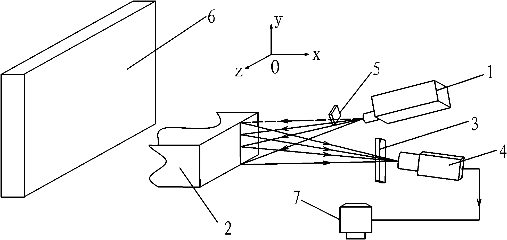
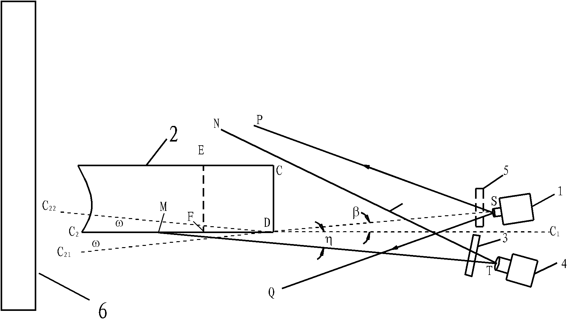
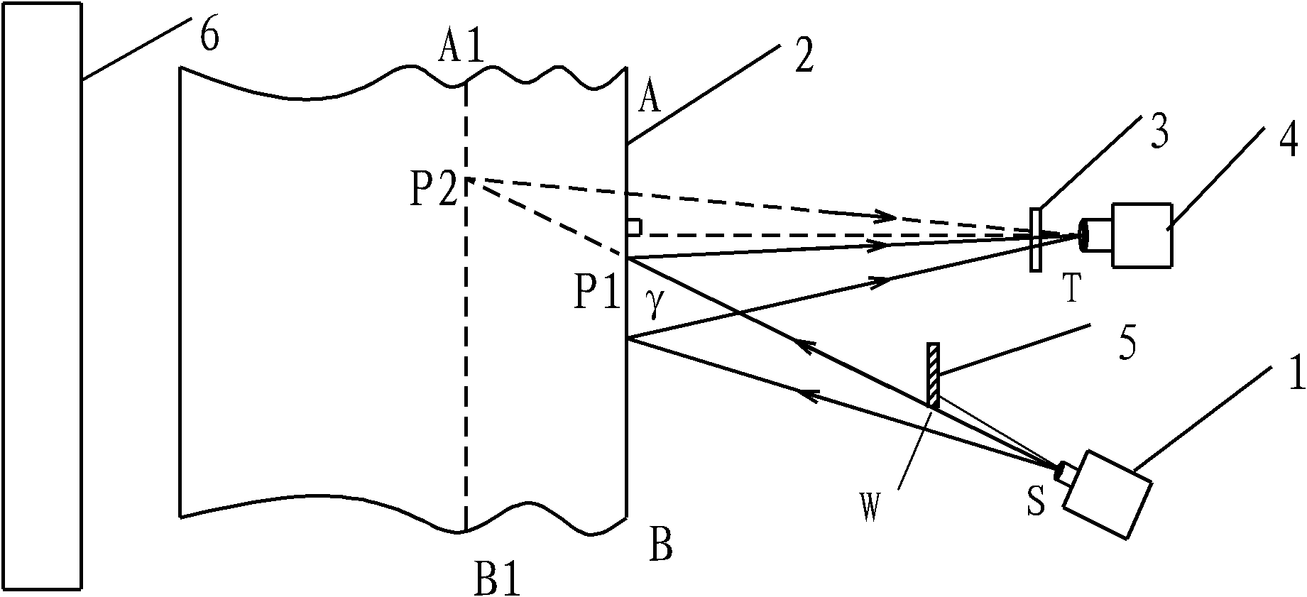

Image

  • Laser measuring device for measuring thickness of plate
  • Laser measuring device for measuring thickness of plate
  • Laser measuring device for measuring thickness of plate

Examples


Embodiment

[0043] figure 2 Among them, the thickness range of the tested board 2 is 120mm, the horizontal distance between the laser outlet and the tested board 2 is 1500mm, and the height from the bottom surface of the tested board 2 is 210.6mm; β=8°

[0044] exist image 3 Among them, the angle between the main axis of the laser and the optical axis of the camera is 26.5°; the angle between the light in the field of view under the camera and the horizontal line is η=8.05°.

[0045] Plate bottom inclination range -8°<ω<8°

[0046] The CCD pixel size of the camera sensor used is: 7.6μm×7.6μm, and the number of pixels is 1600×1200;

[0047] The focal length of the imaging lens used is 75 mm, the horizontal distance between the lens and the tested board 2 is 1500 mm, and the distance between the lens aperture T and the lower surface of the tested board 2 is 240 mm.


PUM


Abstract

The invention discloses a laser measuring device for measuring the thickness of a plate, which comprises a laser, a camera, a black screen and a computer. When the device is used, the laser and the black screen are positioned on two sides of the tested plate; a laser-emitting point S is above the bottom surface of the tested plate; a baffle plate is arranged on the emergent light path of the laser; the baffle plate blocks the laser beam which is about one third of spot diameter; the camera and the laser are positioned on the same side of the tested plate; the incident light hole T of the camera is positioned below the tested plate; an optical filter is arranged in front of a lens of the camera; and the computer is connected with the camera. The measuring method comprises the following steps of: due to the comprehensive utilization of the principles of a laser trigonometry and an optical imaging method, placing the laser slantways to irradiate on the side of a tested object to form a light band; filtering stray light except for the laser wavelength by using the optical filter; and then imaging the light band on a CCD target surface to obtain the thickness value of the tested object through image treatment. Compared with the laser thickness-measuring instrument adopting the double-laser triangle measurement, the laser measuring device has the advantages of convenient installation and great reduction in the high-temperature thermal radiation influence by the tested object.

Description

technical field [0001] The invention belongs to the technical field of linear dimension measurement, and relates to an object thickness measuring device, in particular to a laser measuring device for plate thickness. Since the principle of laser triangulation and optical imaging is comprehensively utilized for laser oblique illumination, it is easy to install and less affected by the high-temperature thermal radiation of the measured object. The invention can be used for plate thickness measurement in metallurgical industry and other fields. Background technique [0002] In order to meet the efficient, accurate and real-time online active measurement requirements of modern industry, various non-contact real-time online measurement methods have emerged. For plate thickness measurement, the non-contact thickness measurement methods used in various production lines at home and abroad are mainly Including ray method, eddy current method, capacitance method, optical method, etc....

Claims


Application Information

Patent Timeline
IPC IPC(8): G01B11/06
Inventor 赵斌王丹熊志勇莫婉玲
Owner HUAZHONG UNIV OF SCI & TECH
Learn More