
Clamping absorption integrated circuit for two-stage matrix converter

A matrix converter and clamp absorption technology, applied in the direction of emergency protection circuit devices, electrical components, etc., to achieve the effects of compact and simple structure, reduced volume and cost, and reduced volume and cost

Inactive Publication Date: 2010-09-08
CENT SOUTH UNIV +1
View PDF6 Cites 14 Cited by
  • Summary
  • Abstract
  • Description
  • Claims
  • Application Information

AI Technical Summary

Problems solved by technology

The two-stage matrix converter is composed of two parts, the current-mode rectification stage and the voltage-mode inverter stage. Due to the uniqueness of the topological structure of the two-stage matrix converter, the clamping and absorbing circuit used in the conventional voltage-mode inverter is used in the two-stage matrix conversion no longer applicable in the

Method used


Image

  • Clamping absorption integrated circuit for two-stage matrix converter
  • Clamping absorption integrated circuit for two-stage matrix converter
  • Clamping absorption integrated circuit for two-stage matrix converter

Examples


Embodiment 1

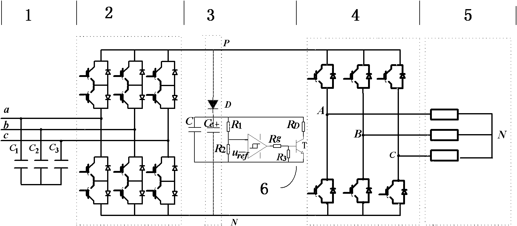
[0027] figure 1 is the topology of a two-stage matrix converter, which consists of an input filter 1 , two-stage matrix converter rectifier stage 2 , clamping circuit 3 , Two-stage matrix converter inverter stage 4 ,load 5 and dual-stage matrix converter clamp absorption integrated circuit 6 composition. The current-mode rectification stage is directly connected to the voltage-mode inverter stage.

[0028] In order to make the three-phase input current sinusoidal and the input end reach unity power factor, it is necessary to use the following modulation method to calculate the duty cycle of the rectifier stage:

[0029] The duty cycle of the rectification stage of the two-stage matrix converter is

[0030] d 1 =sin(kπ / 3-θ-π / 6) (1)

[0031] d 2 =cos(θ-kπ / 3) (2)

[0032] In the formula, k is the sector number where the current reference vector is located, θ is the absolute phase angle of the current reference vector, d 1 is the duty cycle of the kth non-zero vector, ...


PUM


Abstract

The invention provides a clamping absorption integrated circuit for a two-stage matrix converter, which is arranged between the P pole and the N pole of a rectification grade output direct-current bus. The circuit comprises a particular structure that: the positive pole of a diode D is connected with the P pole; an electrolytic capacitor Ce, a high-frequency capacitor C and a voltage bleeder circuit which formed by connecting R1 and R2 in series are connected in parallel between the negative pole of the diode D and the N pole of the rectification grade output direct-current bus; an input end of a hysteresis comparator is connected to a node connecting the R1 and R2, and the output end thereof is connected with the grid of IGBT through a drive resistor Rg; the grid of the IGBT is connected to the N pole through a pull-down resistor; the source of the IGBT is connected with the N pole; and the drain of the IGBT is connected with the negative pole of the diode D through a discharge power resistor RD. The circuit can effectively inhibit invert stage instant overvoltage, can protect overvoltage of the direct current bus, and has the advantages of simple and compact structure and low power consumption and cost.

Description

technical field [0001] The invention belongs to the technical field of power electronics and relates to a clamping and absorbing integrated circuit of a two-stage matrix converter. technical background [0002] The two-stage matrix converter can realize functions such as bidirectional flow of energy, sinusoidal input and output current, and controllable input power factor, and has the advantages of compact structure, low commutation complexity, and low switching loss. It is a green frequency conversion device with broad application prospects. . The two-stage matrix converter is composed of two parts, the current-mode rectification stage and the voltage-mode inverter stage. Due to the uniqueness of the topological structure of the two-stage matrix converter, the clamping and absorbing circuit used in the conventional voltage-mode inverter is used in the two-stage matrix conversion is no longer applicable in the device. Therefore, it is necessary to develop a clamping snubbe...

Claims


Application Information

Patent Timeline
Patent Type & Authority Applications(China)
IPC IPC(8): H02H7/10H02H7/22
Inventor 粟梅孙尧王辉桂卫华王一军于晶荣韩华郭旭东危韧勇李幸周锋封焯文罗朝旭刘见
Owner CENT SOUTH UNIV
Learn More