Electric cooker

A technology of electric cooking utensils and circuits, applied in kitchen utensils, household utensils, electric heating fuel, etc., can solve the problems that affect the cooking effect and food taste, and achieve a good cooking effect

Inactive Publication Date: 2010-09-15
MINGLE DEV (SHENZHEN) CO LTD
View PDF4 Cites 78 Cited by
  • Summary
  • Abstract
  • Description
  • Claims
  • Application Information

AI Technical Summary

Problems solved by technology

As a result, when cooking, the temperature of the induction cooker body can be controlled at the preset temperature, but the actual temperature of the food cannot be controlled, e

Method used


Image

  • Electric cooker
  • Electric cooker
  • Electric cooker

Examples


Embodiment 1

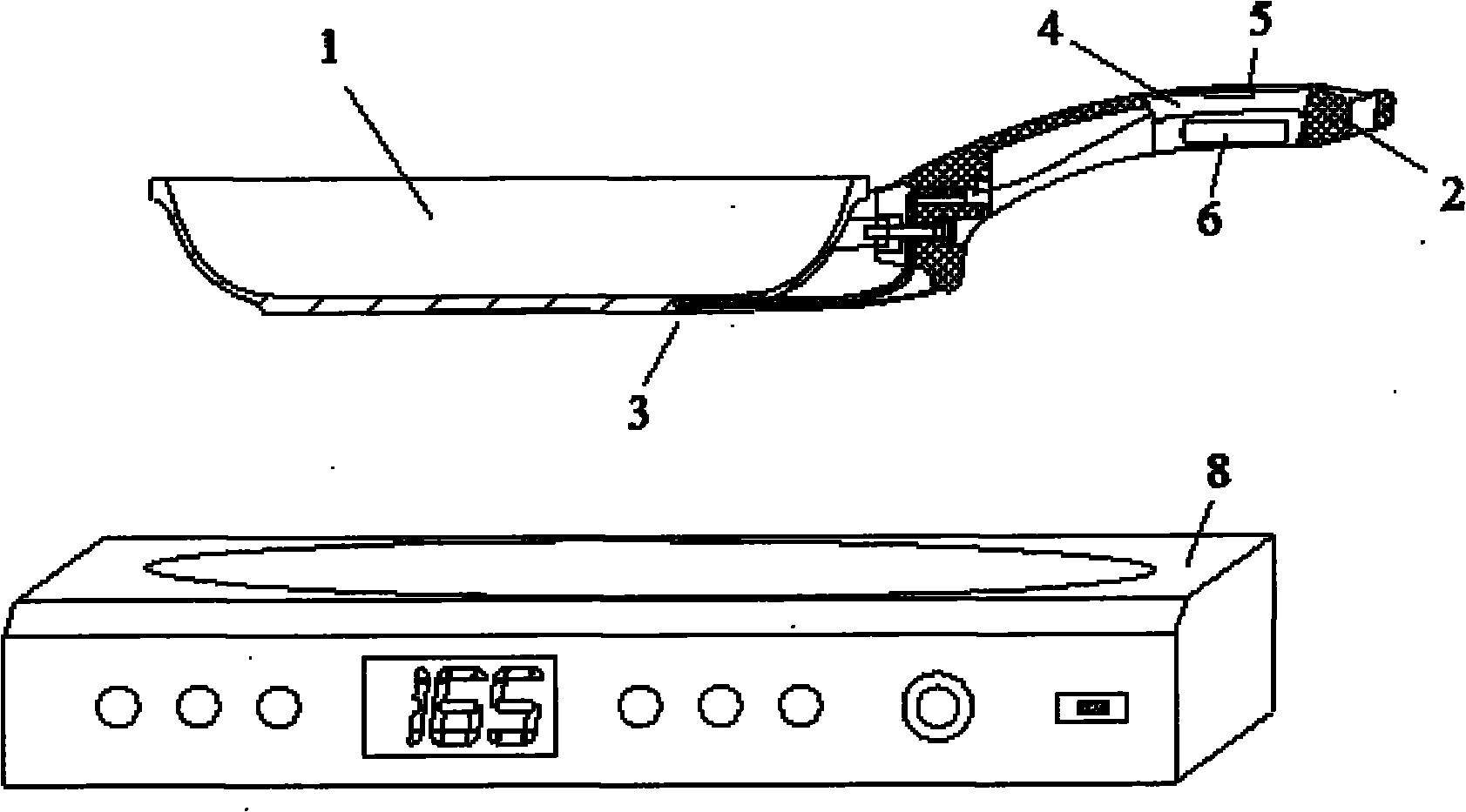
[0044] figure 1 It is a schematic structural diagram of the electric cooker provided in the embodiment of the present application.

[0045] Such as figure 1 As shown, the electric cooker provided by the embodiment of the present application includes: a pot body 1 and an induction cooker body 8 , wherein the pot body 1 is a double-layer pot body with a handle 2 disposed thereon. A first temperature sensor 3 is arranged in the bottom interlayer of the pot body 1 , and a first temperature measuring circuit 4 , a wireless signal transmitting circuit 5 and a DC power supply 6 are arranged in the handle 2 .

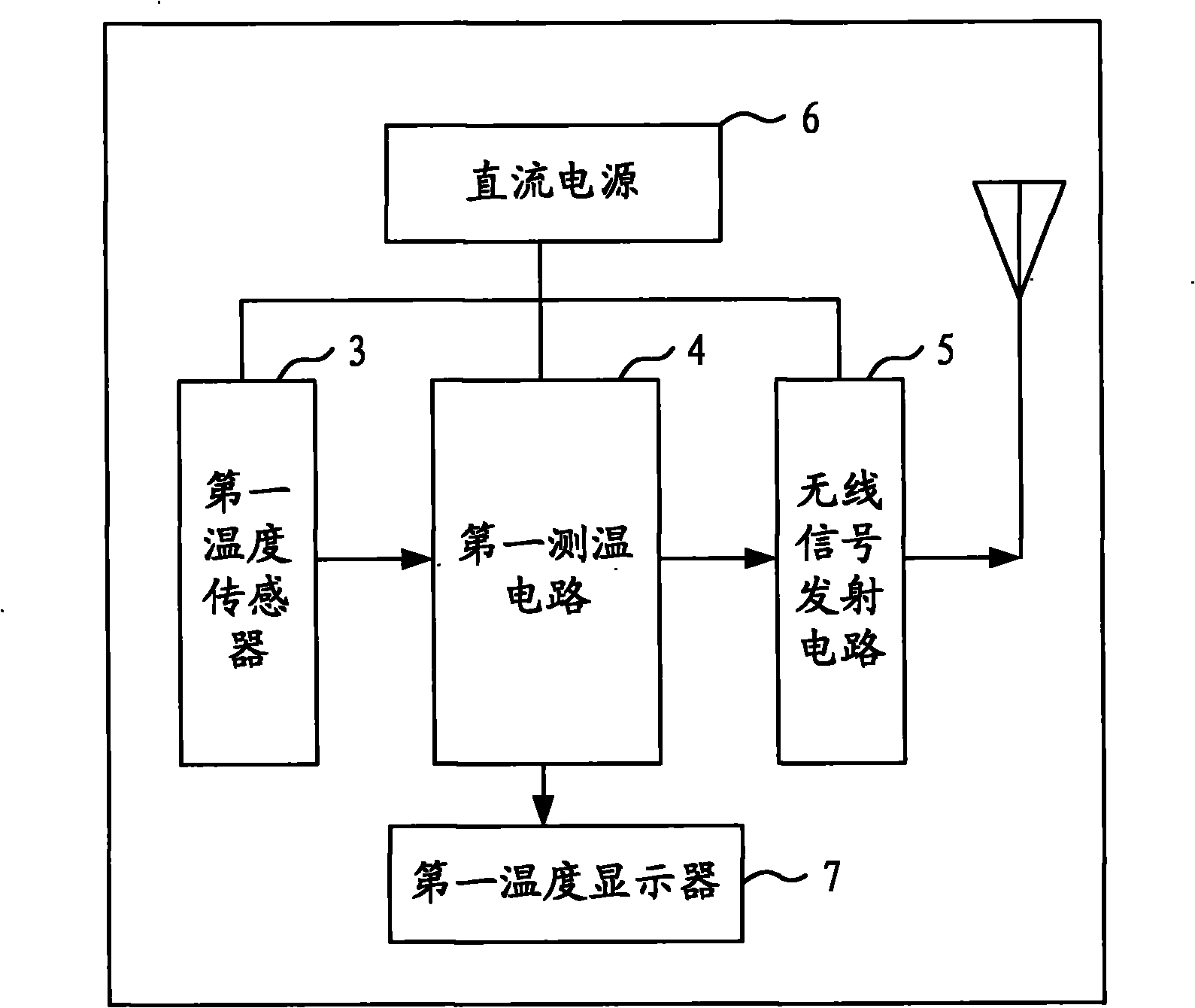
[0046] figure 2 It is a schematic diagram of the circuit structure of the pot provided in the embodiment of the present application.

[0047] Such as figure 2 As shown, the first temperature sensor 3 is used to detect the temperature of the pot body 1, the detected temperature signal is an analog signal, and the detected temperature signal is transmitted to the first temp...

Embodiment 2

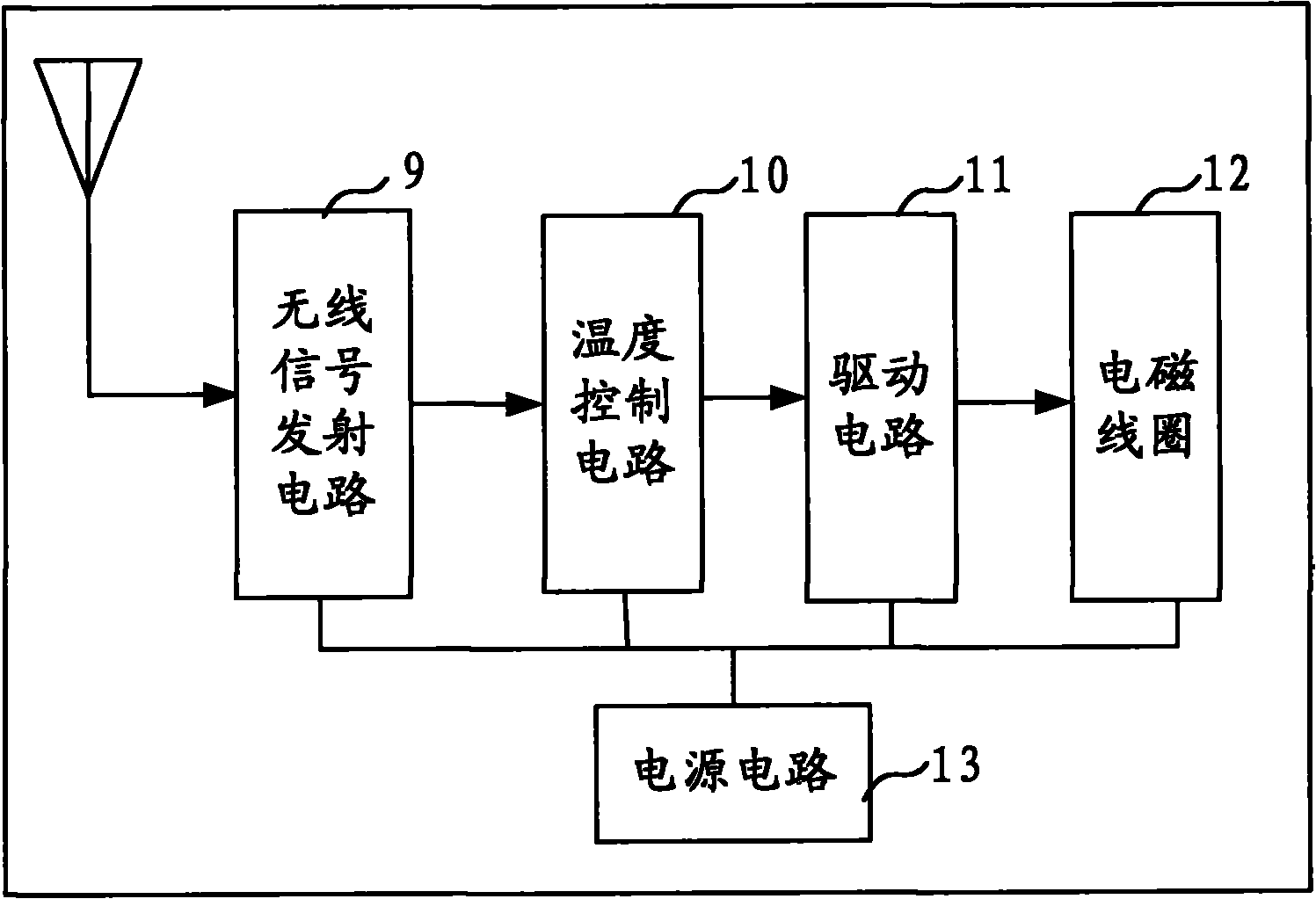
[0053] Figure 6 It is a schematic diagram of another circuit structure of the induction cooker body provided in the embodiment of the present application.

[0054] Such as Figure 6 As shown, the induction cooker body 8 provided in the embodiment of the present application further includes: a second temperature measuring sensor 14 and a temperature control circuit 15 . Wherein the second temperature measuring sensor 14 is used to measure the temperature of the electromagnetic coil 12, and sends the temperature signal to the second temperature measuring circuit 15, and the second temperature measuring circuit 15 sends the temperature signal to the temperature control circuit 10; Based on the temperature signal output control signal sent by the second temperature measuring circuit 15, the control drive circuit 11 is used to receive the control signal of the temperature control circuit 10, and control the power of the electromagnetic coil 12 according to the control signal, and...


PUM


Abstract

The invention discloses an electric cooker comprising a double-layer boiler body with a handle and an electromagnetic oven body, wherein the boiler body comprises a first temperature sensor, a first temperature measuring circuit, a wireless signal transmitting circuit and a direct-current power supply, and the electromagnetic oven body comprises a wireless signal receiving circuit, a temperature control circuit, a drive circuit, an electromagnetic coil and a power circuit. The invention adopts the technical scheme that the temperature sensor is arranged on the boiler body, the temperature control circuit receives temperature signals on the boiler body and controls the output power of the drive circuit according to the temperature signals of the boiler body so as to control the heating temperature of an electromagnetic oven, and then the precise temperature control on heated foods can be realized. In addition, the electromagnetic oven body also comprises a second temperature sensor and a second temperature measuring circuit; and the temperature control circuit can also receives the temperature signals of the electromagnetic oven body and controls the output power of the drive circuit according to the temperature signals of the electromagnetic oven body, thereby realizing the control on the heating temperature of the electromagnetic oven.

Description

technical field [0001] The present application relates to a cooker, in particular to an electric cooker. Background technique [0002] People pay more and more attention to the taste of food, and pay more and more attention to health. It is more and more important for people to adopt accurate temperature control for cooking. [0003] In the induction cooker products currently on the market, the temperature sensor is usually arranged under the panel of the induction cooker, and the temperature sensor is used to measure the temperature of the induction cooker, and then transmitted to the temperature control circuit to control the temperature of the induction cooker. [0004] Through research on the prior art, the applicant found that when cooking in the existing induction cooker, the measured temperature is the temperature of the body of the induction cooker, rather than directly measuring the temperature of the food. As a result, when cooking, the temperature of the inductio...

Claims


Application Information

Patent Timeline
IPC IPC(8): A47J27/00A47J36/00F24C7/08
Inventor 何伟明李明
Owner MINGLE DEV (SHENZHEN) CO LTD
Why Eureka
Try Eureka