Evaporation source device

An evaporation source and evaporator technology, which is applied in vacuum evaporation plating, ion implantation plating, metal material coating processes, etc., can solve the problems of waste, reduce material utilization, and change in evaporation rate, and achieve utilization high effect

Inactive Publication Date: 2015-01-21
EVERDISPLAY OPTRONICS (SHANGHAI) CO LTD
View PDF4 Cites 7 Cited by
  • Summary
  • Abstract
  • Description
  • Claims
  • Application Information

AI Technical Summary

Problems solved by technology

[0005] However, in the organic evaporation process using the above-mentioned evaporation source device, the evaporation material must be preheated, the rate is adjusted, and then the baffle plate blocking the opening of the crucible is opened for evaporation. The evaporation material

Method used


Image

  • Evaporation source device
  • Evaporation source device
  • Evaporation source device

Examples


Embodiment 1

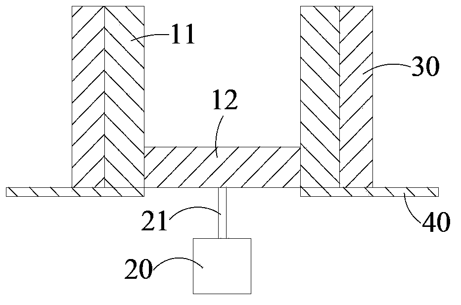
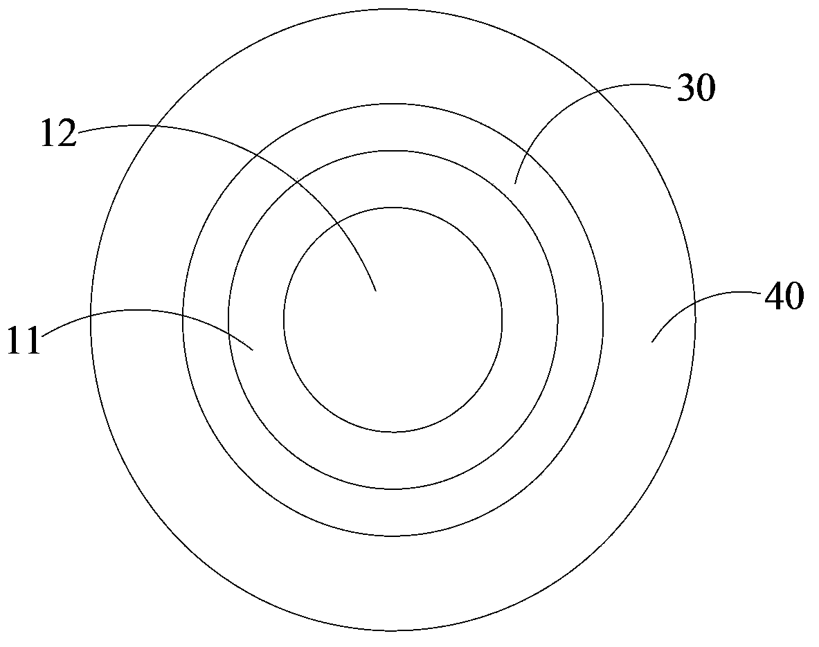
[0047] like figure 1 and figure 2 As shown, the first embodiment of the evaporation source device of the present invention is set in a vacuum chamber (not shown in the figure), and is used for evaporating a thin film on a substrate (not shown in the figure). The evaporation source device includes an evaporator, a lifter and a heater.

[0048] The evaporator is used to evaporate the evaporation material placed in it, and can be made of titanium or white iron. In the first embodiment, the evaporator is a split structure, including a cylinder body 11 and a cylinder base 12 .

[0049] The cylinder 11 is fixedly installed in the vacuum chamber, for example, a baffle 40 is fixed in the vacuum chamber, and the bottom of the cylinder 11 is fixed on the upper surface of the baffle 40 . The top opening of the cylinder 11 is aligned with the substrate, and the cylinder 11 may be a cylinder with a circular cross section, or a straight cylinder with a square cross section or other shap...

Embodiment 2

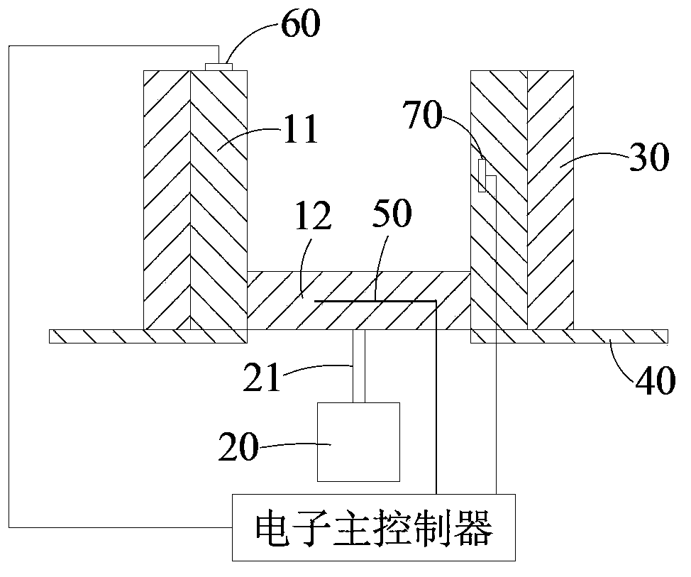
[0055] like image 3 As shown, the second embodiment of the evaporation source device of the present invention adds a controller and an electronic main console on the basis of the first embodiment, the controller can be installed in the electronic main console, and the electronic main console is installed on the baffle 40 below, that is to say, the evaporator is separated from the electronic main console by the baffle plate 40 .

[0056] The controller is used to control the lifter to drive the cylinder base to slide at a constant speed along the barrel. Of course, under the control of the controller, the cylinder base 12 can also slide at a non-uniform speed, but adjusted according to the evaporation parameters.

[0057] In addition, the controller also includes a first temperature sensor 50 arranged on the cylinder base 12, the first temperature sensor 50 is used to sense the temperature data of the cylinder base 12, the controller receives the measured temperature data of t...

Embodiment 3

[0061] like Figure 4 and Figure 5 As shown, the structure of the third embodiment of the evaporation source device of the present invention is basically the same as that of the first embodiment. Nozzles (not shown). At this time, preferably, two linear motors 20 are used, and the ends of the output shafts 21 of the two linear motors 20 are symmetrically connected to the bottom surface of the barrel base 12 . When the cylinder bottom 12 needs to rise or fall, the two linear motors 20 extend or retract the output shafts 21 at the same time. Certainly linear motor 20 also can be replaced by air cylinder or oil cylinder, and at this moment the piston rod end of air cylinder or oil cylinder is symmetrically connected to cylinder base 12 bottom surfaces.


PUM


Abstract

The invention provides an evaporation source device, which is arranged in a vacuum chamber and used for evaporation of film to a substrate. The evaporation source device comprises an evaporator and at least one lifter. The evaporator is used for evaporation of evaporation material placed therein, and comprises a cylinder body and a cylinder seat. The cylinder body is fixedly mounted to the vacuum chamber, the cylinder seat is slidably coupled to the inner wall of the cylinder body. The lifting device is connected to the cylinder seat and used for driving the cylinder seat to move along the cylinder body. In the invention, the evaporator adopts a split structure, and the cylinder seat can be driven by the lifter to move up and down along the cylinder wall. With the usage of evaporation materials, the cylinder seat is rising gradually, so that the distance between the evaporation material and the substrate remains approximately constant to avoid or reduce the residue of evaporation material in the bottom of the evaporator. Accordingly, the evaporation source device provided by the invention can realize high utilization rate of evaporation material.

Description

technical field [0001] The invention relates to an evaporation source device. Background technique [0002] Organic light-emitting diodes (OLEDs) are self-illuminating, have no viewing angle barriers, and have good low-temperature characteristics. Therefore, OLED displays have been considered to be the most valuable new generation of flat-panel displays after liquid crystal displays and plasma displays. [0003] Most OLED manufacturing processes use ITO (indium tin oxide) glass as the substrate, and use evaporation equipment to successively deposit multi-layer thin films on the substrate. [0004] The Chinese invention patent with the publication number CN101942641A proposes a new evaporation source device, including a working platform, a crucible assembly, an evaporation source baffle assembly, and a crucible dredging assembly. The center of the working platform has a working through hole, and at least one set of crucible assemblies and Evaporation source baffle components...

Claims


Application Information

Patent Timeline
IPC IPC(8): C23C14/12C23C14/24
CPCC23C14/12C23C14/24
Inventor 杨红领龚智豪李潍萌
Owner EVERDISPLAY OPTRONICS (SHANGHAI) CO LTD
Why Eureka
Try Eureka