Ceramic floor tile paving device

A technology of floor tiles and ceramics, applied in construction, building structure and other directions, can solve the problems of reducing labor efficiency and subsequent paving quality, laborious handling of workers, and far center of gravity of objects to be handled, achieving good paving quality, reducing labor intensity, Improve the effect of paving work efficiency

Inactive Publication Date: 2010-09-15
JINCHEN GROUP
View PDF0 Cites 33 Cited by
  • Summary
  • Abstract
  • Description
  • Claims
  • Application Information

AI Technical Summary

Problems solved by technology

The leveling operation is a necessary process. Each leveling operation is manually carried and tested ceramic floor tiles. Because the large-scale ceramic floor tiles have a large plane size and weigh up to 10 kilograms, the workers who work in a squatting position open their arms to carry the cantilever. The center of gravity Relatively far away, it

Method used


Image

  • Ceramic floor tile paving device
  • Ceramic floor tile paving device
  • Ceramic floor tile paving device

Examples


Embodiment 1

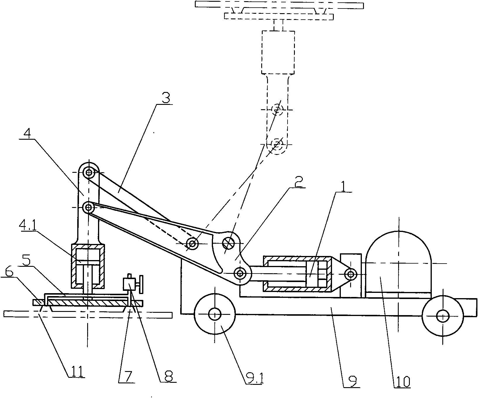
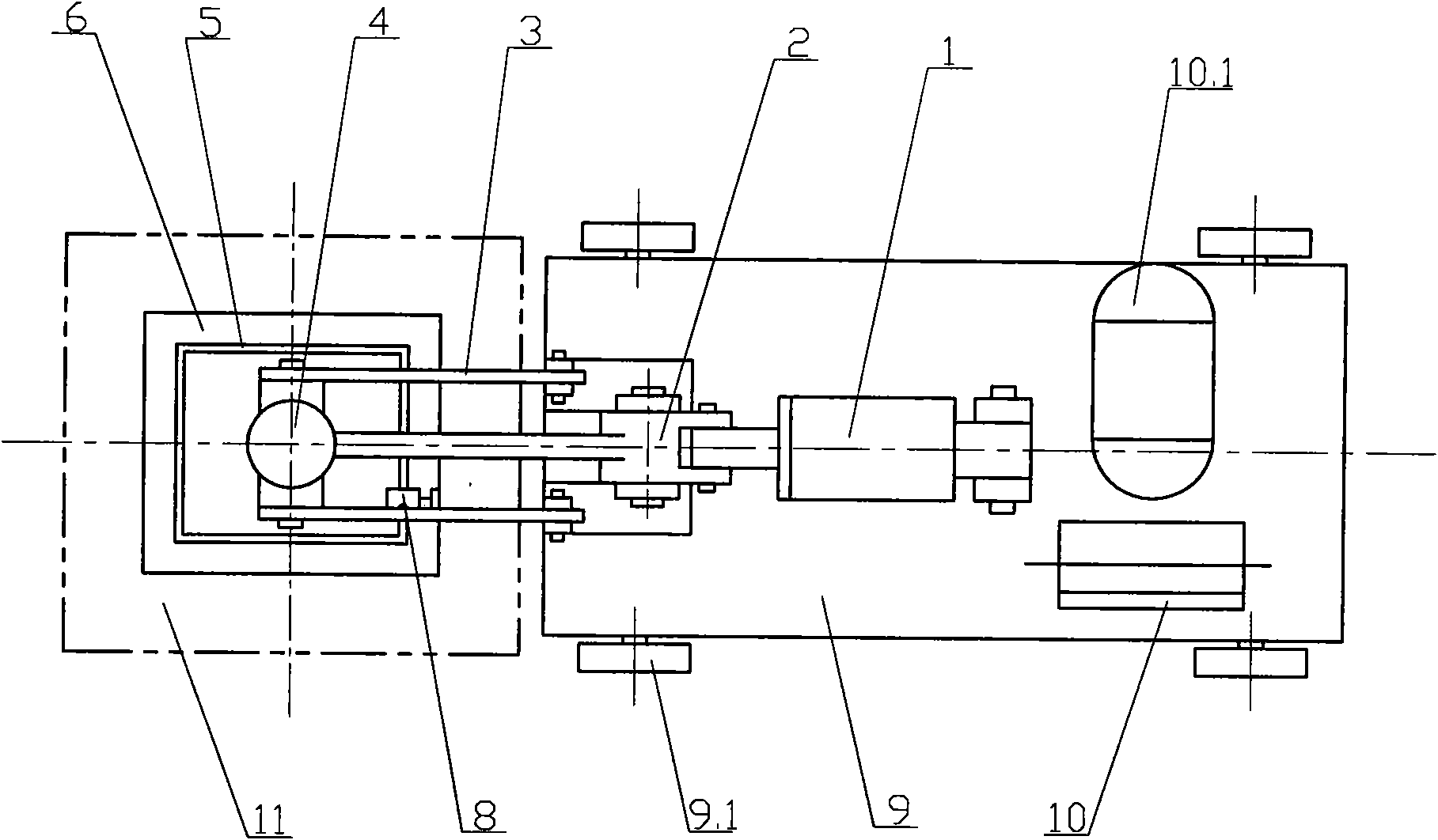
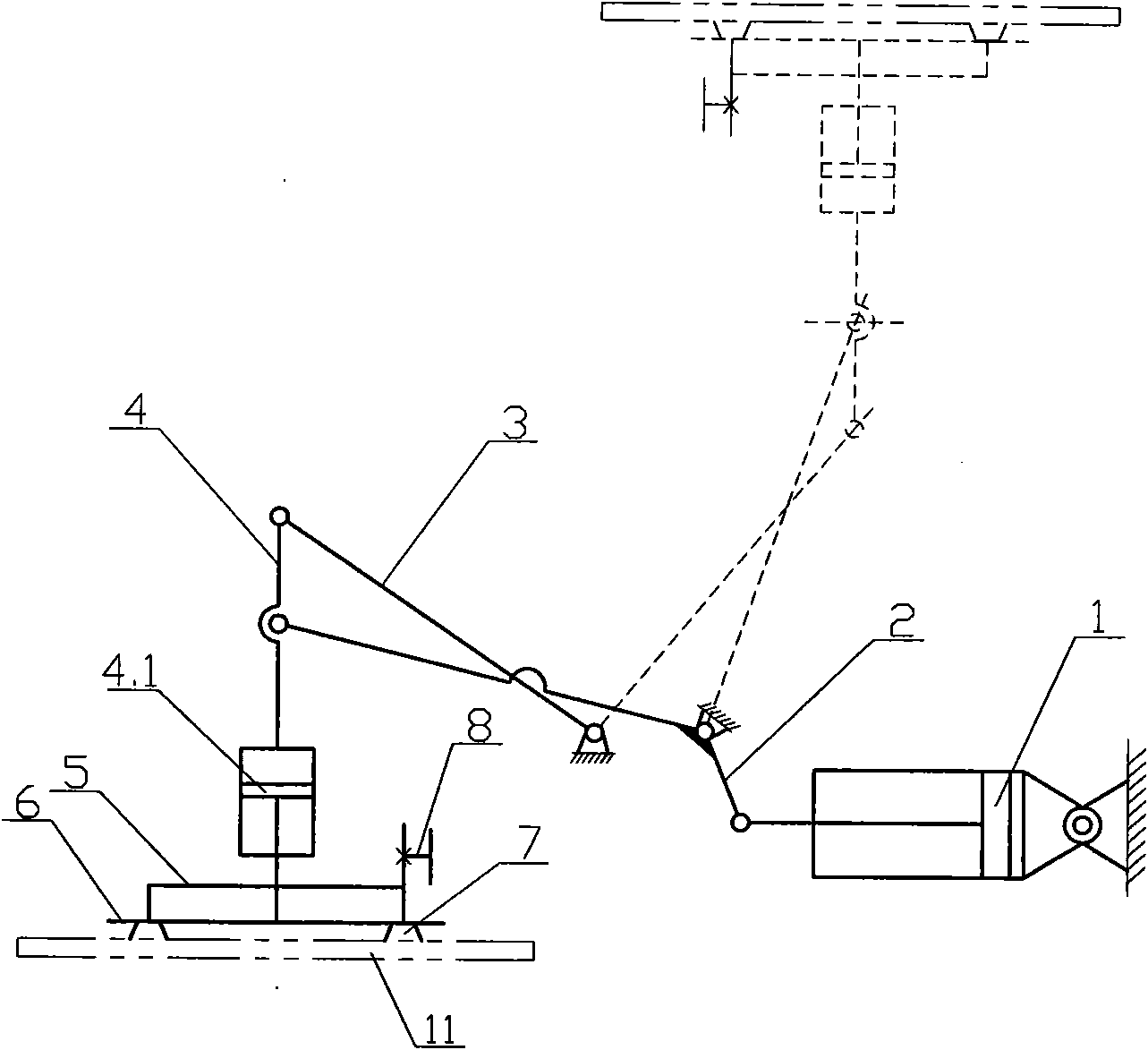
[0017] figure 1 The shown ceramic floor tile tiling device includes a turning mechanism installed on the vehicle frame, a lifting mechanism and a power system. Described vehicle frame comprises flat rectangular bottom plate 9 and the wheel 9.1 that is in rolling contact with the ground, and wheel 9.1 is universal wheel, and vehicle frame is equipped with universal wheel and can move in any direction. Base plate 9 top left ends in the vehicle frame correspond to crank 2, the positioning end of rocking bar 3 to be provided with the boss that is hinged; Turnover mechanism is main mechanism among the present invention, and it is the four-bar linkage mechanism that is driven by master cylinder 1. The overturning mechanism includes connecting rod 4, rocking rod 3 and crank 2. The connecting rod 4 is in a T-shaped structure. 2. The bottom end is hingedly connected with the piston rod of the main cylinder 1, and through the above-mentioned sequential connections, a turning mechanism...

Embodiment 2

[0020] The ceramic floor tile of present embodiment paving is 1200mm * 1200mm, and every piece weighs 48 kilograms. Due to the large area and heavy weight of the workpiece, the corresponding plate 6 was replaced under the condition that the device structure remained unchanged, and the matching suction cup 7 was adjusted to Φ150mm, a total of 9 pieces. Under this condition, the paving of super large ceramic floor tiles 11 is completely satisfied. Requirement, have the same technical effect with embodiment 1.


PUM

PropertyMeasurementUnit
Caliberaaaaaaaaaa

Abstract

The invention discloses a ceramic floor tile paving device. The device comprises a frame, a turnover mechanism, a lifting mechanism and a power system, wherein the frame comprises a bottom plate and universal wheels, the positioning ends, corresponding to a crank and a rocker, at the left end of the bottom plate are provided with protruding platforms used for hinged connection, the middle section of the bottom plate is hinged with a main air cylinder, and the power system is arranged at the right end of the bottom plate; the turnover mechanism is provided with a connecting bar, the rocker and the crank, which are connected in sequence to form a four-bar mechanism which takes the positioning end of the crank as the shaft and can be driven by the main air cylinder to repeatedly overturn 180 degrees; the lifting mechanism uses a secondary air cylinder at the bottom end of the connecting bar as a power component, wherein an extending end of a piston rod is centered and connected with a flat plate; 4 to 9 suction disks, which are connected in series and controlled to be connected or disconnected by a valve, are uniformly distributed on the outer end surface of the flat plate; and the power system is provided with an air compressor and air storage tank, and the main air cylinder and the secondary air cylinder are connected by an air supply tube to form a pneumatic circuit. When the device is used, the ceramic floor tiles which are horizontally placed and wait for paving overturn 180 degrees for vertical descent paving, and because the floor tiles are in parallel contact with a base material, the paving quality is good, the working efficiency is high and the labor intensity of workers is lowered.

Description

technical field [0001] The invention relates to a building construction machine, in particular to a device for laying large ceramic floor tiles. Background technique [0002] In today's era, when people decorate the interior floor of a house, they usually prefer ceramic floor tiles with smooth surface, wear resistance, beauty and low price, especially large square ceramic floor tiles. Large square ceramic floor tiles have a large area, fewer paving joints, and good decorative effects. With the development of modern manufacturing industry, the production process and technical equipment of ceramic floor tile manufacturing industry have also been greatly improved and upgraded, basically meeting the market demand for large ceramic floor tiles, and the specifications of commercial ceramic floor tiles have been expanded from 600mm×600mm to 800mm ×800mm, 1000mm×1000mm, even 1200mm×1200mm. At present, large-scale ceramic floor tiles have become a hot commodity in the sales market....

Claims


Application Information

Patent Timeline
IPC IPC(8): E04F21/22
CPCE04F21/22E04F21/1844E04F21/1888
Inventor 郭如海李焕军刘斌
Owner JINCHEN GROUP
Why Eureka
Try Eureka